
Operating instructions

38
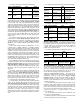
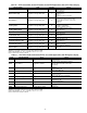
If the Start and End Time remain at the factory default
(0:00), then the unit is not programmed for Night Time/Low
Noise Operation.
To configure this option with the Touch Pilot™ display:
To configure this option with the Navigator™ display:
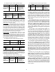
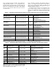
Ramp Loading — Ramp Loading limits the rate of
change of the leaving fluid temperature. If the unit is in a Cool-
ing mode and configured for Ramp Loading Select (Ramp
Loading Select, RL.S), the control makes two comparisons
before deciding to increase capacity. First, the control calcu-
lates the temperature difference between the control point and
leaving fluid temperature. If the difference is greater than 4° F
(2.2° C) and the rate of change (°F or °C per minute) is more
than the configured Cool Ramp Loading rate (Cooling Ramp
Loading, CRMP), then the control does not allow any increase
of capacity.
To configure this option with the Touch Pilot display:
To configure this option with the Navigator display:
Temperature Reset — Temperature reset is a value
added to the basic leaving fluid temperature set point and the
resulting sum of these values is the new control point. When a
non-zero temperature reset is applied, the chiller controls to the
new control point, not the set point. The type of temperature re-
set is configured with the Cooling Reset Type (Cooling Reset
Select, CRST) variable. Four types of temperature reset are
available: Return Water Reset, Outside Air Temperature Reset,
Space Temperature Reset, and 4-20 mA Temperature Reset.
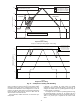
Under normal operation, the chiller will maintain a constant
entering or leaving fluid temperature, based on the configura-
tion, approximately equal to the chilled fluid set point. As the
cooler load varies, the cooler fluid temperature difference will
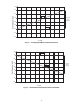
change in proportion to the load. For example, if the chiller was
selected for a Entering to Leaving Water Temperature differ-
ence of 10 F (5.5 C) at full load, at 50% load the temperature
difference would be 5 F (2.2 C). See Fig. 22. Because the
change in temperature through the cooler is a measure of the
building load, the temperature difference reset is the average
building load. Usually the chiller size and fluid temperature set
point are selected based on a full load condition. At part load,
the fluid temperature set point may be lower than required. If
the fluid temperature were allowed to increase at part load, the
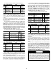
efficiency of the machine would increase. The chiller can also
be set for return water temperature control. See Fig. 23.
Other indirect means of estimating building load and con-
trolling temperature reset are also available and are discussed
below.
To verify that reset is functioning correctly, subtract the Set-
point Select (Current Setpoint, SETP) from the Control Point
(Control Point, CTPT) to determine the degrees reset.
RETURN WATER RESET — The control system is capable
of performing fluid temperature reset based on cooler fluid
temperature difference. Because the change in temperature
through the cooler is a measure of the building load, the tem-
perature difference reset is, in effect, an average building load
reset method.
Return Water Temperature Reset allows for the chilled
water temperature set point to be reset upward as a function of
the fluid temperature difference (building load).
NOTE: Return Water Temperature Reset should not be used
with variable cooler flow rate systems.
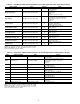
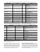
To use Return Water Temperature Reset, four variables
must be configured. Cooling Reset Type (Cooling Reset
Select, CRST) must be enabled. The variable Delta T No Reset
Temp (Delta T No Reset Value, CRT1) should be set to the
cooler temperature difference (T) where no chilled water tem-
perature reset should occur. The variable Delta T Full Reset
Temp (Delta T Full Reset Value, CRT2) should be set to the
cooler temperature difference where the maximum chilled
water temperature reset should occur. The variable Degrees
Cool Reset (Cooling Reset Deg. Value, DGRC) should be set
to the maximum amount of reset desired.
To configure this option with the Touch Pilot display:
DISPLAY NAME PATH
LINE
NO.
VALUE
Start Hour Main Menu
ConfigUser 39 Default: 00:00
End Hour Main Menu
ConfigUser 40 Default: 00:00
Capacity Limit Main Menu
ConfigUser 41 Default: 100%
ITEM ITEM EXPANSION PATH VALUE
LS.ST
Night Low Noise
Start
Configuration
OPTN Default: 00:00
LS.ND
Night Low Noise
End
Configuration
OPTN Default: 00:00
LS.LT
Low Noise Capacity
Lim
Configuration
OPTN Default: 100%
DISPLAY NAME PATH
LINE
NO.
VALUE
Ramp Loading
Select
Main Menu
ConfigUSER
5Yes
Cooling Ramp
Loading
Main Menu
Setpoint
14
Range: 0.2 to 2.0 °F
(0.1 to 1.1 °C)
Default: 1.0 °F (0.5 °C)
ITEM
ITEM
EXPANSION
PAT H VA LUE
RL.S
Ramp Load
Select
Configuration
OPTN Yes
CRMP
Cool Ramp
Loading
Setpoints
COOL
Range: 0.2 to 2.0 °F
(0.1 to 1.1 °C)
Default: 1.0 °F (0.5 °C)
DISPLAY
NAME
PATH
LINE
NO.
VALUE
Cooling Reset
Select
Main
Menu
ConfigUSER
19
Default =0
(No Reset)
2 (Delta T)
Delta T No
Reset Temp
Main
MenuSetpointSETPOINT
7
Default =
0 F (0 C)
Delta T Full
Reset Temp
Main
Menu
SetpointSETPOINT
8
Default =
0 F (0 C)
Cooling Reset
Deg. Value
Main
Menu
SetpointSETPOINT
13
Default =
0 F (0 C)