
Operating instructions

4
“MAIN MENU” Displays the Main Menu screen.
This allows access for viewing and configuration,
where possible, of all points supported by the controller. This
includes points such as set point and operational configuration.
This button is available at all menu levels and returns the user
to the Main Menu screen.
“PREVIOUS” In a group of sequential screens of the
same type, pressing this button moves the user to the
next earlier screen in the group.
“NEXT” In a group of sequential screens of the same
type, pressing this button advances the user to the next
screen in the group.
“OK” Agrees with, or says “yes” to a prompt and per-
forms the appropriate processing.
“NO” Rejects, or says “no” to a prompt and performs
the appropriate processing.
“CANCEL” Terminates an ongoing action and returns
to the current screen without any other processing.
“CLEAR DATA” Clears the data value in a data entry
dialog box. This button is used to clear incorrect data.
“RESET DATA” Zeros the data value in a data entry
dialog box.
“ADD” Adds the active point to a Group Display
screen.
“REMOVE” Deletes a point from a Group Display
screen.
“INCREASE” Modifies the value of a field within its
defined limits or “SCROLL UP” and shifts the screen
view up by one item.
“DECREASE” Modifies the value of a field within its
defined limits or “SCROLL DOWN” and shifts the
screen view down by one item.
“PAGE DOWN” If the current table or list has more
data than will fit on the screen, pressing this button
will replace the items currently on the screen with the next
group of items.
“PAGE UP” If the current table or list has more data
than will fit on the screen, pressing this button will
replace the items currently on the screen with the previous
group of items.
“FORCE” Begins the process of forcing or overriding
the value of a point.
“AUTO” Begins the process of removing a force from
a point.
“MODIFY” Begins the process of modifying a con-
figuration value.
“ALARM INDICATOR LIGHT” An LED alarm
indicator light is activated when a new alarm condi-
tion occurs. The alarm indicator light, located on the
right side of the display, remains activated until it is manually
reset using the Reset button on the Main menu.
“START/STOP BUTTON” The Touch Pilot™ dis-
play includes an equipment Start/Stop Button that
enables the user to start or stop the chiller from the
display. See Enable-Off-Remote Contact Switch (SW1) on
page 17 for additional information.
Several items are password protected. When required, a
Password dialog box will be displayed for field input of the
password. The default password is 3333. The password can be
changed if desired.
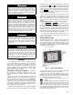
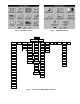
Power-Up Display
— When the Touch Pilot display is pow-
ered up, it displays an initialization progress bar and attaches
(initiates communication) to the Main Base Board. The Touch
Pilot display then shows that controller’s default Group Dis-
play screen. See Fig. 2. This is a user-configured display screen
with up to 9 points on 8 separate screens. For more information
on adding or removing points from the Group Display screen,
see the Group Display Screens section on page 6.
Touch any of the screen point buttons and Point Data Dialog
box will be displayed with expanded information. In the exam-
ple shown below, the CTRL_PNT button in the bottom left
corner was selected. See Fig. 2 and 3.
To exit the box, press .
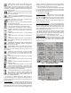
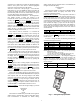
Main Menu Display
— The default screen for the Touch Pilot
controller is the Group Display screen. To access the Main
Menu, press the button. The screen shown in Fig. 4 will be
displayed. Selecting a button will display the screens associat-
ed with that category. The user can also access the login screen
from the Main Menu if needed.
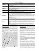
Touch Pilot Menu Structure
— The user can navigate through
the Touch Pilot display screens by selecting the buttons that ap-
pear on the screen. When a button is selected, either a sub-
menu or a list of point names and values will be shown. Sub-
menus will display a list of associated point names. See Fig. 5
for the Touch Pilot menu structure.
If the list of point names and values are shown, the top line
of the display is the table name. The line and total line counter
is displayed in the upper right corner of the display. Selecting
an item will cause a Point Data dialog box to appear.
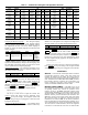
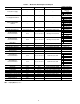
Setup Menu Screen
— The Setup Menu screen, shown in
Fig. 6, is accessed by pressing the Setup button from the Main
Menu. This configuration allows the user to configure the basic
operation and look of the display. Table 1 summarizes the Set-
up Menu functions.
Fig. 2 — Group Display Screen
Fig. 3 — Point Data Dialog Box
a30-4470
a30-4471