
Operating instructions

53
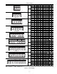
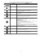
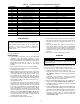
Table 39 — Siemens VFD Control Parameters
*Remove jumper from terminals 5 and 8 (or terminals 5 and 9 for
575 v) before configuring parameter. Reinstall jumper after configu-
ration is complete.
†High Ambient option.
**Standard.
The DIP switches must also be set. DIP switch 1 is not used
and DIP switch 2 is the motor frequency. (OFF = 50 Hz, ON =
60 Hz)
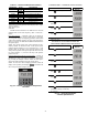
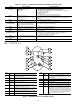
Drive Programming
— Parameter values can be altered via
the operator panel. The operator panel features a five-digit,
seven-segment display for displaying parameter numbers and
values, alarm and fault messages, set points, and actual values.
See Fig. 34 and 35. See Table 40 for additional information on
the operator panel.
NOTE: The operator panel motor control functions are dis-
abled by default. To control the motor via the operator panel,
parameter P0700 should be set to 1 and P1000 set to 1. The
operator panel can be fitted to and removed from the drive
while power is applied. If the operator panel has been set as the
I/O control (P0700 = 1), the drive will stop if the operator
panel is removed.
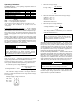
Changing Parameters with the Operator Panel
— See Fig. 35
for the procedure for changing the value of parameter P0004.
Modifying the value of an indexed parameter is illustrated in
Fig. 35 using the example of P0719. Follow the same proce-
dure to alter other parameters using the operator panel.
NOTE: In some cases when changing parameter values the
display on the operator panel displays . This means the
drive is busy with tasks of higher priority.
PARAMETER* VALUE DESCRIPTION
P0010 1 Enter Quick Commissioning
P0311
1140†
Rated Motor Speed
850**
P0757 0.50 Control Signal Scaling Offset
P0761 0.50 Control Signal Scaling Offset
P3900 1 End of Quick Commissioning
P0003 3 User Access Level
P1210 6 Automatic Restart
P1310 10% Continuous Boost
P - - - -
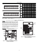
Fig. 34 — Siemens Low Ambient Temperature
Controller
a30-4061
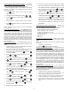
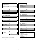
CHANGING P0004 — PARAMETER FILTER FUNCTION
CHANGING P0719 AN INDEXED PARAMETER
SELECTION OF COMMAND/SETPOINT SOURCE
Fig. 35 — Changing Parameters
with the Operator Panel
STEP
RESULT ON
DISPLAY
1 Press to access parameters
2 Press until P0004 is displayed
3 Press to access the parameter
value level
4 Press or to the required
value
5 Press to confirm and store the
value
6 Only the command parameters are
visible to the user.
STEP
RESULT ON
DISPLAY
1 Press to access parameters
2 Press until P0719 is displayed
3 Press to access the parameter
value level
4 Press to display current set value
5 Press or to the required
value
6 Press to conform and store the
value
7 Press until r0000 is displayed
8 Press to return the display to the
standard drive display (as defined by
the customer)
P
P
P
P
P
P
P
P