
Operating instructions

54
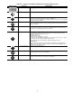
Changing Single Digits in Parameter Values
— For chang-
ing the parameters value rapidly, the single digits of the display
can be changed by performing the following actions:
Ensure the operator panel is in the parameter value chang-
ing level as described in the Changing Parameters with the
Operator Panel section.
1. Press (function button), which causes the farthest
right digit to blink.
2. Change the value of this digit by pressing or .
3. Pressing (function button) again to cause the next
digit to blink.
4. Perform steps 2 to 4 until the required value is displayed.
5. Press (parameter button) to exit the parameter value
changing level.
NOTE: The function button may also be used to acknowledge
a fault condition.
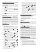
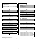
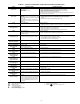
Quick Commissioning (P0010=1)
— It is important that pa-
rameter P0010 is used for commissioning and P0003 is used to
select the number of parameters to be accessed. The P0010 pa-
rameter allows a group of parameters to be selected that will
enable quick commissioning. Parameters such as motor set-
tings and ramp settings are included. At the end of the quick
commissioning sequences, P3900 should be selected, which,
when set to 1, will carry out the necessary motor calculations
and clear all other parameters (not included in P0010=1) to the
default settings. This will only occur in Quick Commissioning
mode. See Fig. 36.
Reset to Factory Default
— To reset all parameters to the fac-
tory default settings, the following parameters should be set as
follows:
1. Jumpers must be in place from terminals 2 and 4 and 5
and 8 (5 and 9 for 575v drives only).
2. Remove the keypad (pull out from top) and verify that
DIP switch 1 is OFF and 2 is ON. Replace keypad.
3. Power up the drive. Press Parameter key. Press
to Parameter P0010.
4. Press , then to change the 0 to a 1. Press
again to accept the change.
5. Press to Parameter P0311. Press and press
to change this value to 1140 for 6-pole motors
or 850 for units with 8-pole motors. Press to accept.
6. Press to Parameter P3900. Press and use
to change this value to 1. Press to accept.
7. The drive will finish standard programming. Remove one
end of the jumper wire from terminal 8.
8. Press again and go to Parameter P0003. Press
and use to change this value to 3. Press to
accept.
9. Press to Parameter P1210. Press and use
to change this value to 6. Press to accept.
10. Press to Parameter P1310. Press and use
to change this value to 10%. Press to accept.
11. Press the Function key and then . The display
will read 0.00 Hz.
12. Replace the wire jumper in terminal 8.
13. The drive is now active. Check fan rotation prior to testing.
If the fan is spinning forward, further adjustment is needed.
Fan should sit still when commanded speed is 0%. If the
fan is spinning forward slightly, press and to
Parameter P0761. Press and use to change this
value to 0.1. Press to accept. Check the fan. If rotation
has stopped no further adjustment is required. If the fan
is still rotating forward, press and use to change
this value to 0.2. Press to accept. Repeat as needed
until the fan is holding still or is just barely moving in
either direction. Do NOT enter a value greater than 0.5
for this parameter without first contacting your Carrier
representative.
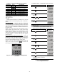
Troubleshooting with the Operating Panel
— Warnings and
faults are displayed on the operating panel with Axxx and
Fxxx. The individual messages are shown in Table 41.
If the motor fails to start, check the following:
• Power is present on T1, T2 and T3.
• Configuration jumpers are in place.
• Control signal between 1 vdc and 10 vdc is present on
terminals 3 and 4.
• P0010 = 0.
• P0700 = 2.
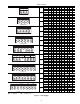
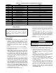
Fault Messages (Tables 41 and 42)
— In the event of a fail-
ure, the drive switches off and a fault code appears on the
display.
NOTE: To reset the fault code, one of the following methods
can be used:
1. Cycle the power to the drive.
2. Press the button on the operator panel.
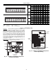
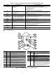
Schneider Altivar VFD Operation
— The low ambient tem-
perature head pressure controller is pre-configured to operate
from a 0 to 10 vdc analog input signal present on terminals
AI1 and COM. A jumper between terminals 24V and LI1 is re-
quired for proper operation. The drive is enabled based on an
increase in the analog input signal above 0 vdc. Output is var-
ied from 0 Hz to 60 Hz as the analog signal increases from
0 vdc to 10 vdc. When the signal is at 0 vdc the drive holds the
fan at 0 rpm. The head pressure control set point is not adjust-
able. The MBB determines the control set point as required.
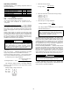
The operating panel is shown in Fig. 37. Refer to the Quick
Start Guide for how to access the programming mode, or the
documentation on CD-ROM (shipped with each VFD) for a
complete set of VFD parameters, fault codes and troubleshoot-
ing information.
Schneider Altivar VFD Replacement
— For Altivar 21
VFDs, if the controller is replaced the parameters in Table 43
must be configured. It is recommended that the configuration
of the VFD is verified per Table 43 prior to proceeding. Also,
the following must be wired:
1. A jumper must be in place from terminal P24 to F.
2. Connect the red and black wires from fan board 0-10
VDC output to terminal VIA and CC respectively.
3. Connect the motor power wires T1, T2 and T3 respec-
tively to terminal U/T1, V/T2 and W/T3 of the drive.
4. Connect the line power wires L1, L2 and L3 from control
box respectively to terminal R/L1, S/L2 and T/L3 of the
drive.
Fn
Fn
P
P
P
P
P
P
P
P
P
P
P
P
P
P
P
Fn
P
P
P
P
P
P
Fn