
Operating instructions

6
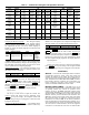
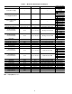
Table 1 — Setup Menu
Setting the Time and Date
— The ComfortLink™ control has
a time and date function. This can be useful for diagnostics to
determine when alarms occur. The control is factory config-
ured for the proper date and is set for the Eastern Time Zone.
The date and time zone must be checked and corrected if nec-
essary, to allow the machine to function on an internal time
schedule and to display a proper time and date stamp for
alarms. The time and date is displayed on the Group Display
Screen.
To change the Time and Date, press the Main Menu
button. Select Time. On the display, a day and date box
with a time box will be shown. To change the day and date,
press the day and date box. A calendar will be displayed. If the
correct month is displayed, touch the correct date. If the wrong
month is displayed, use the or to change to the correct
month and select the correct date. The date will highlighted.
Press to accept the change. The previous screen will be
displayed with the corrected day and date shown. To correct
the time, use the or on the left to change the hour. Use
the or on the left to change the minutes. Continuously
touching the or will sequence the numbers. The time is
shown in a 24-hour format. To accept the changes, press the
or buttons. A “Save” dialog box is displayed with the
words, “Do you wish to save changes?” Press to accept
the changes.
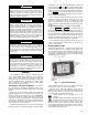
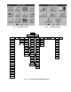
Group Display Screens
— The Touch Pilot™ display sup-
ports up to eight Group Display screens. Group Display
screens show status information along the top of the screens
and nine buttons that display nine point names and point values
that are chosen by the user. All Group Display screen points are
user configurable. The bottom line of the screen contains navi-
gation buttons that can be used to move between the Group
Display screens.
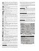
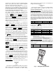
Pressing a point button will show that point’s Point Data
dialog box. See Fig. 2 and 3. This box contains buttons that
remove the point from the group display and apply or remove a
force (point override). When touching any button in the display
screen, the button will be outlined to acknowledge input. There
may be a delay in response to input, but if the button is out-
lined, do NOT press any other button until the previous input
has been processed.
If there is a communication failure with the MBB (Main
Base Board), all point buttons will be displayed in inverse vid-
eo and the message Communication Failure will be displayed
in the top left line of the screen.
Default Group Designation — The default group is the first of
the 8 Group Display screens. This is the default screen of the
display. Information on this screen as well as the other 7
screens can be user-modified to meet the needs of the site.
To Add a Point To a Group Display — From the Main Menu,
press the desired menu button (Status, Setpoint, Service,
Maint, or Config) and, if necessary, the sub-menu button to
access the point to be added. Press the point button to show the
source point’s Point Data dialog box. See Fig. 3. From the
Point Data dialog box, press the ADD button. The display will
show the last Group Display accessed. Use the navigation but-
tons to access the destination Group Display. Press an existing
SETUP MENU BUTTON FUNCTION
REGIONAL
This button specifies the time and date format and the base unit of measure. Time display can be configured as 12-
hour AM/PM setting or as a 24-hour setting. The date can be formatted in one of 3 settings, MM-DD-YYYY (Month-
Day-Year), DD-MM-YYYY (Day-Month-Year), or YYYY-MM-DD (Year-Month-Day). Units of measure can be either US
(English) or Metric (SI).
LANGUAGE
This button selects the active language and font of the display. Available languages are English and Spanish (Espanol).
If a preferred language is not available, additional software for the Main Base Board (MBB) and the Touch Pilot™ dis-
play are required. Contact your Carrier representative for instructions and software.
CONTRAST
This button adjusts the LCD contrast. Press and hold the [MOON] button to increase/darken the contrast or the [STAR]
button to decrease/lighten the current contrast.
NOTE: Touching the screen anywhere for 5 seconds while powering-up will prompt the user to restore contrast and
calibration settings to factory defaults.
BACKLIGHT This button specifies whether backlighting should be kept on at all times or turned off during inactive periods.
CALIBRATE
This button is used to adjust the LCD touch screen calibration. Touch the screen in the circular targets located first in
the upper left and then in the lower right corner of the screen to adjust.
PASSWORDS
This button is used to configure the limited and full logged-in access system passwords. In order to change passwords,
the user must be logged in with full access to view and change the passwords. All passwords must consist of 4-digits,
which can be entered using the numeric keypad. Access levels and associated privileges are as follows:
Limited Logged-in Access - Provides the user with read/write access to all available tables (except service configura-
tion tables, where the user will not be permitted to modify point data, and Group Display tables, where the user will not
be permitted to add points.) This access level also provides read/write access to all Touch Pilot display setup properties
except Display, CCN, and Password.
Full Logged-in Access - Provides user with read/write access to all available tables for the attached device and all
Touch Pilot display properties.
If the user does not log in, read-only access to all tables is allowed. The user will be prompted to log in when attempting
to access password-required functions.
DISPLAY
This button is used to view the description data and part number from the Ctlr-ID Table and to specify the Operating
Mode. The Operating mode can be configured for Equipment mode or Network mode. For Touch Pilot displays that are
standard with the unit, Operating mode should not be changed from Equipment mode. Equipment mode provides
access only to the chiller’s MBB via the Local Equipment Network (LEN) Bus. For remote access, a remote Touch Pilot
display can be set to Network mode. Network mode provides access to all devices on the CCN (Carrier Comfort Net-
work
®
) bus.
NOTE: When changing the operating mode, a power cycle is required in order for the new operating mode to take
effect. The user should view and correct the following CCN data: address and baud rate, alarm acknowledger, and
broadcast acknowledger designation.
CCN This button is used to configure the bus and element numbers and the baud rate of the control on the network.