
Operating instructions

60
Operating Limitations
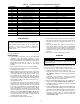
TEMPERATURES — Unit operating temperature limits are
listed in the table below.
LEGEND
*For sustained operation, EWT should not exceed 70 F (21.1 C).
†Unit requires brine modification for operation below this
temperature.
Low Ambient Temperature Operation — If unit operating
temperatures below 32 F (0° C) are expected, refer to separate
unit installation instructions for low ambient temperature oper-
ation using accessory low ambient temperature head pressure
control, if not equipped. Contact your Carrier representative for
details.
NOTE: If wind velocity is expected to be greater than 5 mph
(8 km/h) wind baffles and brackets must be field-fabricated
and installed for all units using accessory low ambient head
pressure control. See the 30XA Installation Instructions or the
low ambient temperature head pressure control accessory
installation instructions for more information.
VOLTAGE
Main Power Supply — Minimum and maximum acceptable
supply voltages are listed in the Installation Instructions.
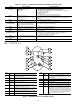
Unbalanced 3-Phase Supply Voltage — Never operate a motor
where a phase imbalance between phases is greater than 2%.
To determine percent voltage imbalance:
The maximum voltage deviation is the largest difference
between a voltage measurement across 2 legs and the average
across all 3 legs.
Example: Supply voltage is 240-3-60.
AB = 243v
BC = 236v
AC = 238v
1. Determine average voltage:
2. Determine maximum deviation from average voltage:
(AB) 243 – 239 = 4 v
(BC) 239 – 236 = 3 v
(AC) 239 – 238 = 1 v
Maximum deviation is 4 v.
3. Determine percent voltage imbalance:
= 1.7%
This voltage imbalance is satisfactory as it is below the
maximum allowable of 2%.
MINIMUM FLUID LOOP VOLUME — To obtain proper
temperature control, loop fluid volume must be at least 3 gal-
lons per ton (3.25 L per kW) of chiller nominal capacity for air
conditioning and at least 6 gallons per ton (6.5 L per kW) for
process applications or systems that must operate at low ambi-
ent temperatures (below 32 F [0° C]). Refer to application in-
formation in Product Data literature for details.
FLOW RATE REQUIREMENTS — Standard chillers should
be applied with nominal flow rates within those listed in the
Minimum and Maximum Cooler Flow Rates table. Higher or
lower flow rates are permissible to obtain lower or higher
temperature rises. Minimum flow rates must be exceeded to
assure turbulent flow and proper heat transfer in the cooler. See
Table 44. See Fig. 38A-38D for cooler pressure drop curves.
Consult application data section in the Product Data
literature and job design requirements to determine flow rate
requirements for a particular installation.
TEMPERATURE F C
Maximum Ambient Temperature 125 52
Minimum Ambient Temperature 32 0
Maximum Cooler EWT* 95 35
Maximum Cooler LWT 60 15
Minimum Cooler LWT† 40 4.4
EWT — Entering Fluid (Water) Temperature
LWT — Leaving Fluid (Water) Temperature
CAUTION
Brine duty application (below 40 F [4.4 C] LCWT) for
chiller normally requires factory modification. Contact a
Carrier Representative for details regarding specific
applications. Operation below 40 F (4.4 C) LCWT with-
out modification can result in compressor failure.
% Voltage Imbalance = 100 x
max voltage deviation from
avg voltage
average voltage
Average voltage =
243+236+238
3
=
717
3
= 239
% Voltage Imbalance = 100 x
4
239
IMPORTANT: If the supply voltage phase imbal-
ance is more than 2%, contact the local electric
utility company immediately. Do not operate unit
until imbalance condition is corrected.
CAUTION
Operation below minimum flow rate could generate
alarms, which could result in damage to the cooler.