
Operating instructions

76
ECONOMIZER EXV CONTROL — The economizer EXV
is controlled by the circuit EXV board. There is an economizer
gas temperature thermistor and economizer pressure transducer
located in the line, which runs from the economizer assembly to
the compressor. The economizer pressure is converted to satu-
rated temperature and is used to calculate economizer superheat.
Economizer superheat equals economizer temperature minus
saturated economizer temperature. The economizer EXV only
operates during normal conditions when the capacity of the
circuit is greater than 75%. Once the capacity of the circuit is
greater than 75% the MBB will start controlling the economizer
EXV to maintain economizer superheat set point, which is ap-
proximately 8° to 12° F (4.4° to 6.7° C). If the circuit capacity is
less than 75%, the economizer EXV will be closed.
The economizer EXV has one override. If the discharge gas
temperature exceeds 195 F (90.6 C) the economizer EXV will
start to open. The EXV will be controlled to maintain discharge
gas temperature at approximately 195 F (90.6 C).
If it appears that main EXV or economizer EXV is not
properly controlling circuit operation to maintain correct super-
heat, there are a number of checks that can be made using test
functions and initialization features built into the microproces-
sor control. See the Service Test section to test EXVs.
EXV TROUBLESHOOTING PROCEDURE — There are
two different economizer EXVs. Both of the economizer
EXVs have a total of 2785 steps. There are three different main
EXVs, which all have a total of 3690 steps. The EXV motor
moves at 150 steps per second. Commanding the valve to
either 0% or 100% will add an additional 160 steps to the
move, to ensure the valve is open or closed completely.
Follow the steps below to diagnose and correct EXV
problems. Check EXV motor operation first. Switch the
Enable/Off/Remote (EOR) Contact switch to the Off position.
Check the appropriate circuit EXV, Circuit A EXV % Open
(Circuit A EXV Position, EXV.A), Circuit B EXV % Open
(Circuit B EXV Position, EXV.B), or Circuit C EXV % Open
(Circuit C EXV Position, EXV.C). The current value of 0 will
be displayed. Increase the EXV position to select 100% valve
position. The actuator should be felt moving through the EXV.
To close the valve, select 0%. The actuator should knock when
it reaches the bottom of its stroke. See Table 48 for a list of
EXV modes and submodes.
If the valve is not working properly, continue with the fol-
lowing test procedure:
Check the 8-position DIP switch on the board for the proper
address (see page 11). Check the EXV output signals at appro-
priate terminals on the EXV module. For 30XA080 units,
connect the positive test lead to EXV-J2A terminal 5 for Circuit
A and to EXV-J2B terminal 5 for Circuit B.
For 30XA090-500 units connect positive test lead to
EXV(X)-J2A terminal 5 for EXV(X) and EXV(X)-J2B termi-
nal 5 for Economizer EXV(X). Using the Service Test proce-
dure on page 105, move the valve output under test to 100%.
DO NOT short meter leads together or pin 5 to any other pin,
as board damage will occur. During the next several seconds,
carefully connect the negative test lead to pins 1,2,3 and 4 in
succession. Digital voltmeters will average this signal and
display approximately 6 vdc. If the output remains at a constant
voltage other than 6 vdc or shows 0 volts, remove the connec-
tor to the valve and recheck.
Select 0% to close the valve.
NOTE: Twelve vdc is the output from the EXV board when
the valve is stationary.
See Tables 6 and 7. If a problem still exists, replace the
EXV board. If the reading is correct, the expansion valve and
EXV wiring should be checked. Check the EXV connector and
interconnecting wiring.
1. Check color-coding and wire connections. Make sure
they are connected to the correct terminals at the EXV
board and EXV plug and that the cables are not crossed.
2. Check for continuity and tight connection at all pin
terminals.
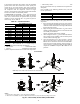
Check the resistance of the EXV motor windings. For
30XA080,082 units remove the EXV module plug EXV-J2A
for Circuit A EXV and EXV-J2B for Circuit B EXV. For
30XA090-500 units remove the EXV module plug EXV(X)-
J2A for main EXV and EXV(X)-J2B for economizer EXV.
Check the resistance of the two windings between pins 1 and 3
for one winding and pins 2 and 4 for the other winding. The
resi
stance should be 52 ohms (± 5.2 ohms). Also check pins 1-4
for any shorts to ground.
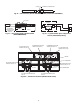
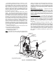
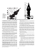
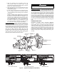
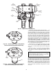
Fig. 47 — Cutaway Views of the Electronic Expansion Valve
1. Cable
2. Glass Seal
3. Motor Housing
4. Stepper Motor
5. Bearing
6. Lead Screw
7. Insert
8. Valve Piston
9. Valve Seat
10. Valve Port
a30-4241