
Operating instructions

78
as an indicator of the slide valve position. Once the calculated
position of the slide valve reaches 100% circuit capacity, the
control will try to increase capacity again if the compressor
current continues to increase. The control will continue to load
the compressor until the compressor current no longer
increases. At that time the control will energize both solenoids
and the circuit will be considered fully loaded.
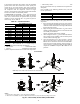
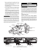
COMPRESSOR OIL SYSTEM — Each compressor/circuit
has its own oil system which includes an oil filter, oil solenoid,
check valve, oil level switch, oil separator heater, oil pressure
transducer, and an oil shut-off valve. A typical oil system is
shown in Fig. 50. See Table 50.
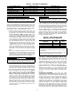
Table 50 — Unit Oil Quantities
Oil Charge
— When additional oil or a complete charge is
required it must meet the following specifications:
• Manufacturer . . . . . . . . . . . . . . . . . . . . . Emkarate RL220XL
• Oil Type . . . . . . . . . . . . . . . . . . . Inhibited polyolester-based
synthetic compressor lubricant for use with screw compressors.
• ISO Viscosity Grade . . . . . . . . . . . . . . . . . . . . . . . . . . . . . 220
Do not reuse drained oil or any oil that has been exposed to the
atmosphere.
Oil is available in the following quantities from your local
Carrier representative:
If unsure if there is low oil charge in the system, follow the
steps below:
1. If the unit shuts off repeatedly from a low oil level alert it
may be an indication of inadequate oil charge; however, it
could also indicate that the oil is not being reclaimed from
the low-side of the system.
2. Begin running the unit at full load for 1
1
/
2
hours. Use the
manual Test Mode feature of Service Test if the unit does
not normally run at full load.
NOTE: An adequate load must be available.
3. After running the unit for 1
1
/
2
hours at full load, allow the
unit to restart and run normally. If low oil alarms persist,
continue with the following steps.
4. Close the liquid line service valve and place a pressure
gage on top of the cooler or suction line service port. En-
able the Service Test feature and turn the Enable/Off/Re-
mote switch to the enable position. Start the desired cir-
cuit by turning it on under the TEST function: CP.A for
compressor A, CP.B for compressor B, or CP.C for com-
pressor C.
30XA UNIT SIZE
OIL CHANGE (gal, [liters])
Circuit A Circuit B Circuit C
080-122 5.5 [20.8] 5.5 [20.8] —
140-162 6.25 [23.7] 5.5 [20.8] —
180-202 6.25 [23.7] 6.25 [23.7] —
220,222 6.75 [25.6] 6.25 [23.7] —
240,242 6.75 [25.6] 6.75 [25.6] —
260,262 7.50 [28.4] 6.75 [25.6] —
280-302 7.50 [28.4] 6.75 [25.6] —
325-352 7.50 [28.4] 7.50 [28.4] —
400 6.75 [25.6] 6.75 [25.6] 7.50 [28.4]
450 7.50 [28.4] 6.25 [23.7] 7.50 [28.4]
500 7.50 [28.4] 6.75 [25.6] 7.50 [28.4]
QUANTITY TOTALINE PART NO.
1 Quart P903-2325
1 Gallon P903-2301
5 Gallon P903-2305
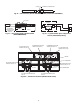
Closed
Open
Closed
Open
EF05BD271
EF05BD331
mm
mm
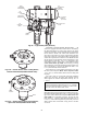
GASKET
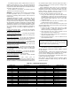
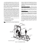
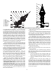
OPEN VALVE IN QUICK TEST SUB-MODE BEFORE DISASSEMBLING
DISASSEMBLY
ASSEMBLY
NOTES:
1. Push down on valve piston to close valve before assembling.
2. After valve is assembled close valve in Quick Test sub-mode or cycle power before opening service valve.
Fig. 48 — Disassembly and Assembly of EXV Motor
NOTE: Open valve in Quick Test sub-mode before disassembling.
a30-4072