
Operating instructions


87
Safety Devices — The 30XA chillers contain many
safety devices and protection logic built into the electronic
control. Following is a description of the major safeties.
COMPRESSOR PROTECTION
Motor Overload
— The compressor protection modules
(CPM) protect each compressor against overcurrent. Do not
bypass the current transformers or make any changes to the
factory-installed and configured headers. The configuration of
these headers defines the Must Trip Amps (MTA) at which the
CPM will turn the compressors off. Determine the cause for
trouble and correct the problem before resetting the CPM. See
Appendix D for MTA settings and configuration headers.
Each CPM board also reads the status of each compressor’s
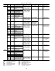
high-pressure switch. All compressors have factory-installed
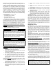
high-pressure switches. See Table 56.
Table 56 — High-Pressure Switch Settings
If the switch opens during operation, the compressor will be
shut down. The CPM will reset automatically when the switch
closes, however, a manual reset of the control is required to
restart the compressor.
OIL SEPARATOR HEATERS — Each oil separator circuit
has a heater mounted on the underside of the vessel. The heater
is deenergized anytime the compressor is on. If the compressor
is off and outdoor-air temperature (OAT) is greater than 100 F
(37.8 C) the heater is deenergized. The heater will also be
deenergized if OAT – SST >32 F (17.8° C) and the OAT –
LWT > 32 F (17.8° C).
COOLER PROTECTION
Low Water Temperature
— Microprocessor is programmed
to shut the chiller down if the leaving fluid temperature drops
below 34 F (1.1 C) for water or more than 8 F (4.4 C) below
set point for Fluid Type = brine. When the fluid temperature
rises 6 F (3.3 C) above the leaving fluid set point, the safety
resets and the chiller restarts. Reset is automatic as long as this
is the first occurrence of the day.
Relief Devices — Fusible plugs are located in each cir-
cuit between the condenser and the liquid line shutoff valve.
PRESSURE RELIEF VALVES — Valves are installed in each
circuit and are located on the coolers and oil separators. These
valves are designed to relieve if an abnormal pressure condition
arises. Relief valves on all coolers relieve at 220 psi (1517 kPa).
Relief valves on oil separators relieve at 350 psi (2413 kPa).
These valves should not be capped. If a valve relieves, it should
be replaced. If the valve is not replaced, it may relieve at a lower
pressure, or leak due to trapped dirt from the system which may
prevent resealing.
See Table 57. Some local building codes require that re-
lieved gases be exhausted to a specific location. This connec-
tion allows conformance to this requirement.
Table 57 — Relief Valve Connection Specs
MAINTENANCE
Recommended Maintenance Schedule —
The fol-
lowing are only recommended guidelines. Jobsite conditions
may dictate that maintenance schedule is performed more often
than recommended.
Routine:
For machines with e-coat condenser coils:
• Check condenser coils for debris; clean as necessary with
Carrier approved coil cleaner.
• Periodic clean water rinse, especially in coastal and indus-
trial applications.
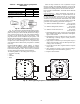
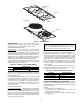
WIRE GUARD
FAN BLADE
FAN DECK
FORMED METAL
MOUNT
MOTOR
Fig. 61 — Fan Mounting
a30-4249
UNIT
SWITCH SETTING
psig kPa
30XA 304.5 +7.25, –14.5 2099 +50, –100
IMPORTANT: If unit is installed in an area where
ambient temperatures fall below 32 F (0° C), a suit-
able corrosion-inhibited antifreeze solution or cooler
heater must be used in the chilled water circuit.
LOCATION CONNECTION SIZES
Oil Separator 3/8 SAE Flare
DX Cooler Option 5/8 SAE Flare
Flooded Cooler Option 3/4 in. NPT Female