
Operating instructions

9
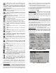
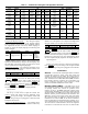
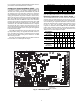
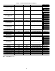
For a complete description of Main Base Board inputs and out-
puts and their channel identifications, see Table 3.
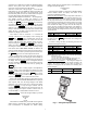
Compressor Protection Module (CPM) — There
is one CPM per compressor. See Fig. 9. The device controls the
compressor contactors, oil solenoid, loading/unloading the
solenoid, motor cooling solenoid (30XA080,082 only) and the
oil separator heater. The CPM also monitors the compressor
motor temperature, high pressure switch, oil level switch, dis-
charge gas temperature, oil pressure transducer, motor current,
MTA (must trip amps) setting and economizer pressure trans-
ducer. The CPM responds to commands from the MBB (Main
Base Board) and sends the MBB the results of the channels it
monitors via the LEN (Local Equipment Network). The CPM
has three DIP switch input banks, Switch 1 (S1), Switch 2 (S2),
and Switch 3 (S3). The CPM board DIP switch (S1) configures
the board for the type of starter, the location and type of the
current transformers and contactor failure instructions. See Ta-
ble 4 for description of DIP switch 1 (S1) inputs. See Appendix
D for DIP switch settings.
The CPM board DIP switch S2 setting determines the must
trip amps (MTA) setting. See Appendix D for DIP switch set-
tings. The MTA setting which is calculated using the settings
S2 must match the MTA setting in the software or an MTA
alarm will be generated.
See below for CPM board DIP switch S3 address informa-
tion. See Table 5 for CPM inputs and outputs.
NOTE: The CPM-A and CPM-B DIP switches are for all
units. The CPM-C DIP switches are for 30XA400-500 units.
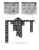
Electronic Expansion Valve (EXV) Board —
The 30XA080,082 unit has one EXV board. The 30XA090-
500 units have one EXV board per circuit. See Fig. 10. The
board is responsible for monitoring the suction gas temperature
and economizer gas temperature thermistors. The board also
signals the main EXV and economizer EXV (ECEXV) motors
to open or close. The electronic expansion valve board
responds to commands from the MBB and sends the MBB the
results of the channels it monitors via the LEN (Local Equip-
ment Network). See below for DIP switch information. See
Tables 6 and 7 for EXV inputs and outputs.
CPM-A DIP Switch 1 2 3 4
Address: OFF OFF OFF OFF
CPM-B DIP Switch 1 2 3 4
Address: OFF OFF ON OFF
CPM-C DIP Switch 1 2 3 4
Address: OFF OFF OFF ON
EXV BOARD A
(080-500)
DIP SWITCH
123456 7 8
Address: ON ON ON ON ON ON OFF ON
EXV BOARD B
(090-500)
DIP SWITCH
1 23456 7 8
Address: OFF ON ON ON ON ON OFF ON
EXV BOARD C
(400-500)
DIP SWITCH
1 2 3456 7 8
Address: ON OFFONONONONOFFON
221
221
221
221
195
195
195
195
195
195
195
CH1 CH2 CH3
CH4
CH11 CH12
LOCATION OF
SERIAL NUMBER
CH13
CH14
CH
15A
J4
ANALOG
INPUTS
J3
J2C
J2B
24 VAC
J1A
+ G –
DISCRETE
INPUTS
J5A
CH
15a
11
C16
J2A
TR1 TR2 TR3 TR4 TR5
CH19 CH20 CH21 CH22 CH23 CH24 CH25 CH26
J8
CH17
CH18
J5B
J5C
THERMISERS PRESSURES
CH5
CH6 CH7 CH8 CH9
J7A J7B J7C J7D
RELAY
OUTPUTS
MOV1
C41
C42 C43
C32
C33
C34
C35
12/11
12/11
J10
LEN
+ G -
STATUS
J9A
K1
K2
D15
J6
CCN
CH10
+ G –
SIO
(LEN)
J9C
J9B
+ G –
LEN
LEN
CCN J13 J9D
+
C
+
C
CH
16a
+
C
CH
16b
Fig. 8 — Main Base Board
a30-4255