AQUAFORCE® 30XW150-400 Water-Cooled Liquid Chillers Controls, Start-Up, Operation, Service and Troubleshooting CONTENTS Page SAFETY CONSIDERATIONS . . . . . . . . . . . . . . . . . . . . .2,3 GENERAL . . . . . . . . . . . . . . . . . . . . . . . . . . . . . . . . . . . . . . 3-9 Conventions Used in This Manual . . . . . . . . . . . . . . . . 3 Display Module Usage . . . . . . . . . . . . . . . . . . . . . . . . . . . 3 • TOUCH PILOT™ DISPLAY • NAVIGATOR™ DISPLAY MODULE CONTROLS . . . . . . . . . . . . . .
CONTENTS (cont) WARNING Page • ECONOMIZER EXV CONTROL • EXV TROUBLESHOOTING PROCEDURE • INSPECTING/OPENING ELECTRONIC EXPANSION VALVE Compressor Assembly . . . . . . . . . . . . . . . . . . . . . . . . . . 67 • COMPRESSOR OIL SYSTEM Cooler . . . . . . . . . . . . . . . . . . . . . . . . . . . . . . . . . . . . . . . . . . .
show an expanded description of the point name. To view the expanded point name for the Touch Pilot™ display refer to Appendix A. CAUTION To prevent potential damage to heat exchanger tubes, always run fluid through heat exchanger when adding or removing refrigerant charge. Use appropriate antifreeze solutions in evaporator and condenser fluid loops to prevent the freezing of heat exchangers or interconnecting piping when the equipment is exposed to temperatures below 32 F (0° C).
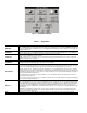
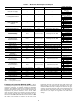
Setup Menu Screen — The Setup Menu screen, shown in Fig. 6, is accessed by pressing the Setup button from the Main Menu. This configuration allows the user to configure the basic operation and look of the display. Table 1 summarizes the Setup Menu functions. “ADD” adds the active point to a Group Display screen. “REMOVE” deletes a point from a Group Display screen. “INCREASE” modifies the value of a field within its defined limits or “SCROLL UP” shifts the screen view up by one item.
User interface Group display x 8 Status Schedule Service Maint Config Alarms GENUNIT OCC1PO1S FACTORY LOADFACT Ctrl-ID ALARHIST Regional CIRCA_AN OCC2PO2S FACTORY2 FANCTRL DISPCONF ALARHIS2 Language CIRCA_D SERVICE1 M_MSTSLV USER ALAM_CUR Contrast CIRCB_AN CP_UNABL DEFROSTM MST_SLV Backlight CIRCB_D UPDTHOUR LAST_POR CFG_TAB1 Calibrate CIRCC_D UPDHRFAN PR_LIMIT … Password CIRCC_AN MAINTCFG BOARD_PN … Display STATEGEN SERMAINT CFG_TAB8 CCN RECLAIM EXV_CTRL
a30-4474 Fig. 6 — Setup Menu Display Table 1 — Setup Menu SETUP MENU BUTTON REGIONAL LANGUAGE CONTRAST BACKLIGHT CALIBRATE PASSWORDS FUNCTION This button specifies the time and date format and the base unit of measure. Time display can be configured as 12-hour AM/PM setting or as a 24-hour setting. The date can be formatted in one of 3 settings, MM-DD-YYYY (MonthDay-Year), DD-MM-YYYY (Day-Month-Year), or YYYY-MM-DD (Year-Month-Day). Units of measure can be either US (English) or Metric (SI).
with the source point’s name. Press to add the highlighted point to the group and return to the table display. To Remove a Point from a Group Display — From the Point Data Dialog box, press the REMOVE button and follow the prompts. The display will return to the Group Display screen from which the point was removed, and the button corresponding to the deleted point will be blank and disabled.
Adjusting the Contrast — The contrast of the display can be adjusted to suit ambient conditions. To adjust the contrast, enter the LED Test mode of the device. This indicates an initialization period while the Navigator™ display initiates communication with the Main Base Board. Once communication is established, the default rotating display will be shown.
Table 2 — ComfortLink Navigator™ Display Menu Structure RUN STATUS Auto Display (VIEW) Machine Starts/Hours (RUN) Compressor Run Hours (HOUR) Compressor Starts (STRT) Fan Run Hours (FAN) Compressor Disable (CP.
Table 3 — Main Base Board Inputs and Outputs CONNECTION POINT Pin Notation MBB-J1, MBB-J1A, MBB-J1B 11 24 vac 12 Ground MBB-J9A, MBB-J9B, MBB-J9C, MBBJ9D + RS485 Port (D+) G RS485 Port (Gnd) RS485 Port (D-) MBB-J12 + RS485 Port (D+) G RS485 Port (Gnd) RS485 Port (D-) MBB-J5B-CH17 17 MBB-J4-CH13 16A MBB-J5A-CH16A MBB-J7A-CH6 5V +5 vdc Ref. S Signal R Return MBB-J7C-CH8 5V +5 vdc Ref.
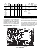
DIP SWITCH 2 (S2) C CH 06 C CH 10 CH 12 CH 11 CH 13 CH 14 12 11 J10B J10A R R CH02 CH01 DG MOT TMP J9 TMP J11 J2 CH 05 R S 5 CH03 R SMT S 5 CH04 OIL PRESS 24 VDC/OLL LOADERS OLS MOTOR COOLING 151 1 R20 ECO AUX PRESS 2 2 151 HPS 151 151 2x 151 2x 151 561 DIP SWITCH 3 (S3) 561 561 561 151 102 151 151 151 102 620 0N 102 102 102 1 2 3 4 101 S3 CT1 CT2 LOCATION OF SERIAL NUMBER MTA K40 0N CT3 1 2 3 4 5 6 7 8 S2 J8 K40 0N S1 1 2 3 4 5 6 7 8 151 151 J4
Table 5 — Compressor Protection Module Inputs and Outputs* DESCRIPTION INPUT/OUTPUT I/O TYPE DISPLAY MODULE POINT NAME Power (24 vac supply) — — — Local Equipment Network — — — Circuit X High Pressure Switch HPS-X Switch Not available CONNECTION POINT Pin Notation CPM-X-J1 11 24 vac 12 Ground CPM-X-JP12 1 RS485 Port (D+) 2 RS485 Port (Gnd) 3 RS485 Port (D-) CPM-X-J12 1 RS485 Port (D+) 2 RS485 Port (Gnd) 3 RS485 Port (D-) CPM-X-J7-CH05 1 2 CPM-X-J6-CH06 Oil Level Switch Oil LS X Switch Ci
Electronic Expansion Valve (EXV) Board — EXV BOARD 1 (150-400) DIP SWITCH Address: The 30XW150-325, 375 units have one EXV board. The 30XW350,400 units have one EXV board per circuit. See Fig. 10. The board is responsible for monitoring the suction gas temperature and economizer gas temperature thermistors. The board also signals the main EXV and economizer EXV (ECEXV) motors to open or close.
Table 6 — EXV1 Board Inputs and Outputs (30XW150-325, 375) DESCRIPTION INPUT/OUTPUT I/O TYPE DISPLAY MODULE POINT NAME Power (24 vac supply) — — — Local Equipment Network — — — Circuit A Suction Gas Thermistor SGTA 5k Thermistor Compressor Suction Temp, SGT.A Circuit B Suction Gas Thermistor SGTB 5k Thermistor Compressor Suction Temp, SGT.B Circuit A EXV EXV-A Stepper Motor EXV Position, EXV.A Circuit B EXV (size 325 only) EXV-B Stepper Motor EXV Position, EXV.
for auxiliary board A, B and C DIP switch addresses. See Table 8 for inputs and outputs. Minimum Load Valve (MLV) / Condenser Board — One auxiliary board is optionally installed in each unit. See Fig. 11. The auxiliary board contains an analog output for head pressure control and discrete outputs for minimum load control. The auxiliary board responds to commands from the MBB and sends the MBB the results of the channels it monitors via the Local Equipment Network (LEN).
Energy Management Module (EMM) — The EMM Enable-Off-Remote Contact Switch (SW1) — is available as a factory-installed option or as a field-installed accessory. See Fig. 12. The EMM receives 4 to 20 mA inputs for the temperature reset, cooling set point and demand limit functions. The EMM also receives the switch inputs for the field-installed second stage 2-step demand limit and ice done functions.
Table 9 — Energy Management Module (EMM) Inputs and Outputs INPUT/OUTPUT 4-20 mA Demand Limit 4-20 mA Temperature Reset/Cooling Setpoint Demand Limit SW2 Ice Done Occupancy Override Remote Lockout Switch SPT % Total Capacity RUN R SHD R CA_S CB_S DESCRIPTION 4-20 mA Demand Limit 4-20 mA Temperature Reset/ Cooling Set point Demand Limit Step 2 Ice Done Switch Occupied Schedule Override Chiller Lockout Space Temperature Thermistor Percent Total Capacity Output Run Relay Shutdown Relay Run Status for Circuit
To connect the unit to the network: 1. Turn off power to the control box. 2. Cut the CCN wire and strip the ends of the red (+), white (ground), and black (–) conductors. (Substitute appropriate colors for different colored cables.) 3. Connect the red wire to (+) terminal on TB3 of the plug, the white wire to COM terminal, and the black wire to the (–) terminal. 4.
Table 12 — Touch Pilot™ Controller Identification Configuration Table CONTROLLER ID DATA BLOCK NO.
BROADCAST ACKNOWLEDGER — This configuration is used to indicate whether the Touch Pilot™ display will act as the broadcast acknowledger for its CCN bus. There can be only one broadcast acknowledger per CCN bus. NOTE: The display must be in Network mode and this decision set to Yes for broadcast acknowledgement to be enabled.
Schedule 2 is used for Dual Set Point/Occupied-Unoccupied set point control. The control will ignore the position of Enable/Off/Remote Contact switch and all CCN network force commands, except the Emergency Stop Command. The Run Status variable will indicate the current status of the machine — OFF, RUNNING, DELAY, or READY. The Chiller Occupied? variable will indicate the occupied state of the machine according to Time Schedule 1 and will be either YES (occupied) or NO (unoccupied).
on a one-time basis. To configure this option for the Touch Pilot display: DISPLAY NAME PATH Timed Override Config\OCCDEFCS\ Hours OCC1P01S or OCC1P02S Table 15 — Configuring the Schedule with Touch Pilot™ Display PATH LINE NO. 1 2 Config\ OCCDEFCS\ OCC1P01S or OCC1P02S 3 4 5 VALUE 11111000 06:00 18:30 00000110 10:00 14:00 00000001 12:00 14:00 00000000 00:00 24:00 00000000 00:00 24:00 Holiday Schedule — For the Touch Pilot™ display, the control allows up to 16 holiday periods.
NAVIGATOR™ DISPLAY MACHINE CONTROL — Machine On/Off control with the Navigator™ display is determined by the configuration of the Operating Type Control (OPER). Options to control the machine locally via a switch, from a local Time Schedule, or via a Carrier Comfort Network® command are offered. See Table 17. The schedules consist of 8 user-configurable occupied time periods. The control supports time schedules for local control, remote control, and ice building.
Time Schedule — With Time Schedule Operating Type control, the machine operates under a local schedule programmed by the user as long as the Enable/Off/Remote Contact switch is in the Enable or Remote Contact position (external contacts closed). To operate under this Operating Type Control (OPER) must be set to TIME SCHED (Time Schedule). Two Internal Time Schedules are available and must be field programmed. Time Schedule 1 (SCH1) is used for single set point On-Off control.
Heat/Cool Select (HC.SE) = 1 (Heating) allows the unit to operate in the heating mode only. Heat/Cool Select (HC.SE) = 3 (Heat Cool Sw) allows the unit to switch between cooling and heating based on a dry contact input (open contacts = Cool, closed contacts = Heat). Use of the Heat/Cool switch option requires field installed wiring to Main Base Board input channel 14. Refer to 30XW wiring diagram in Service Test section. Heat/Cool Select can also be forced from communications (CCN point name HC_SEL).
Table 21B — Cooling Set Point Selection with Navigator™ Display ITEM ITEM EXPANSION PATH CSP.1 Cooling Setpoint 1 Setpoints COOL CSP.2 Cooling Setpoint 2 Setpoints COOL CSP.3 Ice Setpoint Setpoints COOL CAUTION Brine duty application (below 40 F [4.4 C] LCWT) for chillers normally requires factory modification. Contact a Carrier Representative for details regarding specific applications. Operation below 40 F (4.4 C) LCWT without modification can result in compressor failure.
Set Point 1 — When Set Point Select (Setpoint Select, SP.SE) is configured to 1 (Setpoint 1), the unit’s active set point is based on Cooling Set Point 1 (Cooling Setpoint 1, CSP.1). To configure this option with the Touch Pilot™ display: DISPLAY NAME LINE NO. 25 PATH Status GENUNIT Setpoint Select rectification. A signal isolation device should be utilized if a full wave bridge signal generating device is used. The following equation is used to control the set point. See Fig. 18.
Heating Set Point Selection — Several options for Table 24B — Heating Set Point Selection with Navigator™ Display 30XW chillers operating as heat machines exist for controlling the Leaving Condenser Water Set Point and are configured by the Set Point Select (Setpoint Select, SP.SE) variable. In addition, the Heat Cool Select (Heat/Cool Select, HC.SE) variable also has a role in determining the set point of the machine. All units are shipped from the factory with the Heat/Cool Select set to 0.
the chilled water pump interlock contact (connected across TB5 terminals 1 and 2) are required. In addition, for Cooler Pumps Sequence settings of PUMP = 1, 2, 3, 4, normally open auxiliary contacts for Pump 1 and Pump 2 (wired in parallel) must be connected to the violet and pink wires located in the harness from the MBB-J5C-CH18 connector. The wires in the harness are marked "PMP1-13" and "PMP1-14". See the field wiring diagram in the 30XW Installation Instructions.
Single Pump Control — To configure condenser pump control options with the Touch Pilot™ display: Dual Pump and Manual Control — To configure cooler pump control options with the Touch Pilot™ display. DISPLAY NAME LINE NO.
On both chillers, Master/Slave Select (Master/Slave Select, MSSL) must be enabled. The water piping arrangement, Chillers in Series (Chiller in Series, SERI), must be configured. The master chiller must be programmed with the Slave Chiller Address (Slave Address, SLVA). Additional optional programming parameters may be configured to meet application requirements. Lead/Lag Balance Select (Lead Lag Select, LLBL) determines which chiller is the lead machine.
chiller for series applications using the Navigator™ display, see Table 32. DUAL CHILLER PUMP CONTROL FOR SERIES CHILLER APPLICATIONS — Pump control for series chiller applications is controlled by the master chiller only. The control of the slave chiller is directed through commands emitted by the master chiller. The slave chiller has no action in master/slave operations. The slave chiller only verifies that CCN communication with the master chiller is present.
Table 27 — Dual Slave Chiller Control Parameters for Parallel Applications with Touch Pilot™ Display DISPLAY NAME PATH LINE NO.
Table 29 — Dual Master Chiller Control Parameters for Series Applications with Touch Pilot™ Display DISPLAY NAME PATH LINE NO.
Table 31 — Dual Slave Chiller Control Parameters for Series Applications with Touch Pilot™ Display DISPLAY NAME PATH LINE NO.
Ramp Loading — Ramp Loading limits the rate of change of the leaving fluid temperature. If the unit is in a Cooling mode and configured for Ramp Loading Select (Ramp Loading Select, RL.S), the control makes two comparisons before deciding to increase capacity. First, the control calculates the temperature difference between the control point and leaving fluid temperature. If the difference is greater than 4° F (2.
To configure this option with the Navigator™ display: ITEM CRST CRS1 CRS2 DGRC ITEM EXPANSION PATH Configuration RSET Cooling Reset Type Setpoints COOL Space T No Reset Temp Space T Full Reset Temp Setpoints COOL Degrees Cool Reset Setpoints COOL CAUTION VALUE Default = No Reset Space Temp Default = 14 F (–10 C) Default = 14 F (–10 C) Default = 0 F (0 C) Care should be taken when interfacing with other control systems due to possible power supply differences such as a full wave bridge versus
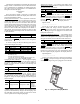
56 EWT 54 Fluid Temperature (deg F) 52 50 Design Rise (typical) LWT 48 a30-4478 46 44 42 40 0 10 20 30 40 50 60 70 80 90 100 % Load Fig. 20 — Return Water Temperature Control Load Profile 6 5 Degrees Reset (deg F) 4 Cooling Reset Deg. Value, DGRC 3 Delta T No Reset Temp, CRT1 2 Delta T Full Reset Temp, CRT2 1 a30-4479 0 0 2 6 4 Entering-Leaving Water Temperature (deg F) Fig.
7 6 Degrees Reset (deg F) 5 4 Cooling Reset Deg. Value, DGRC 3 Space T No Reset Value, CRS1 2 Space T Full Reset Value, CRS2 1 a30-4481 0 60 65 70 75 80 Space Temperature (deg F) Fig. 22 — Space Temperature Reset 6 Degrees Reset (deg F) 5 4 Cooling Reset Deg. Value, DGRC 3 Current No Reset Value, CRV1 2 Current Full Reset Value, CRV2 1 a30-4482 0 0 2 4 6 8 10 12 14 mA Signal Fig.
To configure this option with the Navigator™ display: Demand Limit — Demand limit is a feature that allows the unit capacity to be limited during periods of peak energy usage. This allows the owner to keep energy costs down. There are three types of demand limiting that can be configured. The first type is through 2-step switch control, which will reduce the maximum capacity to 2 user configurable percentages.
To configure this option with the Touch Pilot™ display: EXTERNALLY POWERED (4 to 20 mA) CAPACITY BASED DEMAND LIMIT — The energy management module is required for 4 to 20 mA demand limit control. An externally powered 4 to 20 mA signal must be connected to TB6-1 and TB6-2. To configure demand limit for 4 to 20 mA control based on unit capacity, four parameters must be configured.
100 90 80 % Demand Limit 70 60 mA For 0% Demand Limit, DMZE 50 40 a30-4831 30 mA For 100% Demand Limit, DMMX 20 10 0 2 0 4 12 8 10 mA Demand Limit Signal 6 14 16 20 18 Fig. 24 — 4 to 20 mA Demand Limit (Capacity) 2000 1800 1600 Compressor Current 1400 1200 mA For 0% Demand Limit, DMZE 1000 800 600 mA Fo r 100% Demand Limit, DMMX 400 a30-4832 200 0 0 2 4 6 8 10 12 14 16 18 20 mA Signal Fig.
RE-ALARM TIME — This variable specifies the amount of time that will be allowed to elapse between re-alarms. A realarm occurs when the conditions that caused the initial alarm continue to persist for the number of minutes specified in this decision. Re-alarming will continue to occur at the specified interval until the condition causing the alarm is corrected. This variable can only be changed with the Touch Pilot display, ComfortVIEW software, or Network Service Tool.
DESCRIPTION Alarm Routing 0 0 0 STATUS 0 0 0 0 0 POINT ALRM_CNT ComfortView™, or ComfortWorks® TeLink Unused a30-4485 BacLink or DataLink™ Unused Fig. 26 — Alarm Routing Control Override # 9: Demand Limit — This override mode is active Capacity Control Overrides — The following cawhen a command to limit the capacity is received. If the pacity control overrides (Active Capacity Override, CAP.
compressor capacity changes, an additional 90-second delay will be added to Override #13 delay. No compressor will be deenergized until 3 minutes have elapsed since the last compressor has been turned ON. When this override is active, the capacity control algorithm calculations will be performed, but no capacity reduction will be made until the timer has expired. A control with higher precedence will override the Minimum On Time Delay.
2. If the leaving fluid temperature is 3.6 °F (2 °C) or more below the freeze setpoint (LOSP), the compressor capacity will be decreased when discharge gas temperature exceeds 190 F (87.8 C). If after five minutes, the discharge gas temperature falls below 175 F (79.4 C), the compressor will be allowed to load again.
5. Open discharge, liquid line, oil line, and economizer (if equipped) service valves. 6. Fill the chiller fluid circuit with clean water (with recommended inhibitor added) or other non-corrosive fluid to be cooled. Bleed all air out of high points of system. If unit is exposed to temperatures below 32 F (0° C), sufficient inhibited propylene glycol or other suitable corrosion inhibited antifreeze should be added to the chiller water and condenser water circuit to prevent possible freeze-up.
2. Determine maximum deviation from average voltage: (AB) 243 – 239 = 4 v (BC) 239 – 236 = 3 v (AC) 239 – 238 = 1 v Maximum deviation is 4 v. 3. Determine percent voltage imbalance: Table 35 — Temperature Limits for Standard Units TEMPERATURE Maximum Condenser EWT Minimum Condenser EWT Maximum Condenser LWT* Maximum Cooler EWT† Maximum Cooler LWT Minimum Cooler LWT** F 110 65 118 70 60 40 C 43.3 18.3 47.8 21.1 15.6 4.
Table 36 — Evaporator and Condenser Flow Rates 30XW UNIT 150 175 185 200 225 250 260 275 300 325 350 375 400 Two pass One pass Three pass Two pass One pass Three pass Two pass One pass Three pass Two pass One pass Three pass Two pass One pass Three pass Two pass One pass Three pass Two pass One pass Three pass Two pass One pass Three pass Two pass One pass Three pass Two pass One pass Three pass Two pass One pass Three pass Two pass One pass Three pass Two pass One pass Three pass EVAPORATOR
(kPa) ft wg (119.4) 40.00 (104.4) 35.00 3 pass 1 pass Pressure Drop (89.5) 30.00 2 pass (74.6) 25.00 (59.7) 20.00 (44.8) 15.00 (29.8) 10.00 (14.9) 5.00 (0) 0.00 0 (0) 500 (31.5) 1000 (63.1) 1500 (94.6) 2000 gpm (126.2) (L/s) Evaporator Flow Rate NOTE: The table above represents pressure drops only. The table does not imply that the chiller can be properly applied over the entire range of evaporator water flow rates represented. a30-4833 Fig.
(kPa) ft wg (119.4) 40.00 (104.4) 35.00 Pressure Drop 2 pass (89.5) 30.00 3 pass 1 pass (74.6) 25.00 (59.7) 20.00 (44.8) 15.00 (29.8) 10.00 (14.9) 5.00 (0) 0.00 0 (0) 500 (31.5) 1000 1500 (63.1) (94.6) Evaporator Flow Rate 2000 (126.2) 2500 gpm (157.7) (L/s) NOTE: The table above represents pressure drops only. The table does not imply that the chiller can be properly applied over the entire range of evaporator water flow rates represented. Fig.
(kPa) ft wg (119.4) 40.00 2 pass 3 pass 1 pass (104.4) 35.00 Pressure Drop (89.5) 30.00 (74.6) 25.00 (59.7) 20.00 (44.8) 15.00 (29.8) 10.00 (14.9) 5.00 (0) 0.00 0 (0) 500 (31.5) 1000 1500 (63.1) (94.6) Evaporator Flow Rate 2000 (126.2) 2500 gpm (157.7) (L/s) LEGEND NIH — Nozzle-In-Head NOTE: The table above represents pressure drops only. The table does not imply that the chiller can be properly applied over the entire range of evaporator water flow rates represented. Fig.
(kPa) ft wg (119.4) 40.00 Pressure Drop 1 pass 3 pass (104.4) 35.00 2 pass (89.5) 30.00 (74.6) 25.00 (59.7) 20.00 (44.8) 15.00 (29.8) 10.00 (14.9) 5.00 (0) 0.00 0 (0) 500 (31.5) LEGEND NIH — Nozzle-In-Head 1000 1500 (63.1) (94.6) Evaporator Flow Rate 2000 gpm (126.2) (L/s) NOTE: The table above represents pressure drops only. The table does not imply that the chiller can be properly applied over the entire range of evaporator water flow rates represented. A30-4692 Fig.
(kPa) ft wg (119.4) 40.00 40.0 3 pass (104.4) 35.00 35.0 Prressure Drop (89.5) 30.00 30.0 2 pass (74.6) 25.00 25.0 1 pass (59.7) 20.00 20.0 15.00 (44 8) 15 (44.8) 1500 15.0 0 (29.8) 10.00 10.0 (14.9) 5.00 5.0 (0) 0.00 0.0 00 (0) 500 500 (31.5) 1000 1000 (63.1) 1500 (94.6) 2000 2000 gpm (126.2) (L/s) Condenser Flow Rate NOTE: The table above represents pressure drops only.
(kPa) ft wg (119.4) 40.00 40.0 (104.4) 35.00 35.0 Pressure Drop 3 pass (89.5) 30.00 30.0 2 pass (74.6) 25.00 25.0 1 pass (59.7) 20.00 20.0 (44.8) 15.00 15.0 (29.8) 10.00 10.0 (14.9) 5.00 5.0 (0) 0.00 0.0 0 (0) 500 (31.5) 1000 (63.1) 1500 1500 (94.6) 2000 2000 (126.2) 2500 2500 (157.7) 3000 3000 (189.3) 3500 3500 gpm (220.8) (L/s) Condenser Flow Rate NOTE: The table above represents pressure drops only.
(kPa) ft wg (119.4) 40.00 40.0 (104.4) 35.00 35.0 3 pass ssure Drop Pres (89.5) 30.00 30.0 2 pass (74.6) 25.00 25.0 1 pass (59.7) 20.00 20.0 (44.8) 15.00 15.0 (29.8) 10.00 10.0 (14.9) 5.00 5.0 (0) 0.00 0.0 0 (0) 500 500 (31.5) 1000 1000 (63.1) 1500 1500 (94.6) 2000 2000 (126.2) 2500 gpm 2500 (157.7) (L/s) Condenser Flow Rate LEGEND NIH — Nozzle-In-Head NOTE: The table above represents pressure drops only.
(kPa) ft wg (119.4) 40.00 (104.4) 35.00 2 pass Pressure Drop (89.5) 30.00 (74.6) 25.00 (59.7) 20.00 (44.8) 15.00 (29.8) 10.00 (14.9) 5.00 (0) 0.00 0 (0) 500 (31.5) 1000 (63.1) 1500 (94.6) 2000 (126.2) gpm (L/s) Condenser Flow Rate LEGEND NIH — Nozzle-In-Head NOTE: The table above represents pressure drops only. The table does not imply that the chiller can be properly applied over the entire range of evaporator water flow rates represented. A30-4837 Fig.
(kPa) ft wg (119.4) 40.00 (104.4) 35.00 Pressure Drop 2 pass (89.5) 30.00 (74.6) 25.00 (59.7) 20.00 (44.8) 15.00 (29.8) 10.00 (14.9) 5.00 (0) 0.00 0 (0) 500 (31.5) 1000 (63.1) 1500 (94.6) 2000 (126.2) 2500 (157.7) 3000 (189.3) 3500 gpm (220.8) (L/s) Condenser Flow Rate LEGEND NIH — Nozzle-In-Head NOTE: The table above represents pressure drops only. The table does not imply that the chiller can be properly applied over the entire range of evaporator water flow rates represented. A30-4696 Fig.
Point, CTPT). The mode will terminate when the Temperature Reset is not modifying the active leaving water set point, causing SETP to be the same as CTPT. DEMAND LIMIT ACTIVE — This mode is checked for when the unit is ON. The mode is active when Demand Limit (Demand Limit Type Select, DMDC) is enabled either by DMDC=1 (Switch), DMDC=2 (4-20 mA Input), or the Night Time Low Sound Capacity Limit (Capacity Limit, LS.LT).
For a fresh water system (Cooler Fluid Type, FLUD =1), the freeze point is 34° F (1.1° C). For medium temperature brine systems, (Cooler Fluid Type, FLUD=2), the freeze point is Brine Freeze Set Point (Brine Freeze Setpoint, LOSP). For criterion 1, no additional capacity will be added. For criteria 2 and 3 capacity will be decreased on the circuit. The mode will terminate when the circuit’s SST is greater than the freeze point minus 6° F (3.3° C) or the circuit has alarmed.
one SEN terminal and connect the other wire to the other SEN terminal located under the cover of the space temperature sensor. 2. Connect the other ends of the wires to terminals 7 and 8 on TB6 located in the unit control box. Units on the CCN can be monitored from the space at the sensor through the RJ11 connector, if desired. To wire the RJ11 connector into the CCN: 1. Cut the CCN wire and strip ends of the red (+), white (ground), and black (–) conductors.
Table 39A — 5K Thermistor Temperature (°F) vs Resistance TEMP (F) –25 –24 –23 –22 –21 –20 –19 –18 –17 –16 –15 –14 –13 –12 –11 –10 –9 –8 –7 –6 –5 –4 –3 –2 –1 0 1 2 3 4 5 6 7 8 9 10 11 12 13 14 15 16 17 18 19 20 21 22 23 24 25 26 27 28 29 30 31 32 33 34 35 36 37 RESISTANCE (Ohms) 98,010 94,707 91,522 88,449 85,486 82,627 79,871 77,212 74,648 72,175 69,790 67,490 65,272 63,133 61,070 59,081 57,162 55,311 53,526 51,804 50,143 48,541 46,996 45,505 44,066 42,679 41,339 40,047 38,800 37,596 36,435 35,313 34,231 3
Table 39B — 5K Thermistor Temperature (°C) vs Resistance TEMP (C) –32 –31 –30 –29 –28 –27 –26 –25 –24 –23 –22 –21 –20 –19 –18 –17 –16 –15 –14 –13 –12 –11 –10 –9 –8 –7 –6 –5 –4 –3 –2 –1 0 1 2 RESISTANCE (Ohms) 100,260 94,165 88,480 83,170 78,125 73,580 69,250 65,205 61,420 57,875 54,555 51,450 48,536 45,807 43,247 40,845 38,592 38,476 34,489 32,621 30,866 29,216 27,633 26,202 24,827 23,532 22,313 21,163 20,079 19,058 18,094 17,184 16,325 15,515 14,749 TEMP (C) 3 4 5 6 7 8 9 10 11 12 13 14 15 16 17 18 19 20
ECTA (175, 200, 250, 275, 300, 350, 400 ONLY) DGTA EPTA (175, 200, 250, 275, 300, 350, 400 ONLY) HPSA A30-4838 EPTB (350, 400 ONLY) ECTB (350, 400 ONLY) DGTB HPSB OPTB SGTB OPTA DGT DPT ECT EPT HPS OPT SGT SPT — — — — — — — — LEGEND Discharge Gas Thermistor Discharge Pressure Transducer Economizer Gas Thermistor Economizer Pressure Transducer High-Pressure Switch Oil Pressure Transducer Suction Gas Thermistor Suction Pressure Transducer SGTA *Not visible from angle shown.
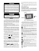
Electronic Expansion Valve (EXV) — See Fig. 49 BRASS NUT 3/8 - 24 FOR ASSEMBLY ON BRASS WELL O-RING a30-4079 for a cutaway view of the EXV. High-pressure liquid refrigerant enters valve through the top. As refrigerant passes through the orifice, pressure drops and refrigerant changes to a 2-phase condition (liquid and vapor). The electronic expansion valve operates through an electronically controlled activation of a stepper motor.
325,375 units, connect the positive test lead to EXV-J2A terminal 5 for Circuit A and to EXV-J2B terminal 5 for Circuit B. For 30XW175,200,250,275,300,350,400 units connect positive test lead to EXV(X)-J2A terminal 5 for EXV(X) and EXV(X)-J2B terminal 5 for Economizer EXV(X). Using the Service Test procedure on page 88, move the valve output under test to 100%. DO NOT short meter leads together or pin 5 to any other pin, as board damage will occur.
Table 40 — EXV Modes and Submodes EXV TYPE AND CIRCUIT EXV, Circuit A EXV, Circuit B Economizer EXV, Circuit A Economizer EXV, Circuit B TOUCH PILOT™ PATH Main Menu Status QCK_TST1 Q_EXVA Main Menu Status QCK_TST1 Q_EXVB Main Menu Status QCK_TST1 Q_ECO_A Main Menu Status QCK_TST1 Q_ECO_B INSPECTING/OPENING ELECTRONIC EXPANSION VALVES NAVIGATOR™ PATH Service Test Mode QUIC EXV.A Service Test Mode QUIC EXV.B Service Test Mode QUIC ECO.A Service Test Mode QUIC ECO.
DISASSEMBLY CLOSED 27mm / 11/16'' OPEN NOTE: Open valve in Quick Test sub-mode before disassembling. OPEN VALVE IN QUICK TEST SUB-MODE BEFORE DISASSEMBLING ASSEMBLY CLOSED 50Nm (36 ft-lb)+ 30° 27mm / 11/16'' OPEN GASKET EF05BD271 NV 32.5mm EF05BD331 NV 36mm NOTES: 1. Push down on valve piston to close valve before assembling. 2. After valve is assembled close valve in Quick Test sub-mode or cycle power before opening service valve. Fig.
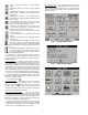
SUCTION TEMPERATURE DISCHARGE GAS THERMISTOR HIGH PRESSURE SWITCH MOTOR TEMPERATURE SENSOR 1 COMMON MOTOR TEMPERATURE SENSOR 2 ACCESS FITTING Unloader Piston Chamber Slide Valve D isch arg e P ort t ex t Slide Valve l Loaded Loaded Position Posi tion Trapped Oil at High Pressure t ext D is ch ar g e Po r t B leed Line to Low Pressure Suction High Pressure Oil Bleed Line to Low Pressure Suction High Pressure Oil Energized F L OW Val ve #1 (NC) De- energized FLOW Valve #2 ( NO) FULLY LOADED O
Replacing the Oil Filter — Close the oil line ball valve located in front of the oil filter. Connect a charging hose to the 1/4-in. access fitting port located downstream of the valve and bleed off oil trapped between the service valve and the oil solenoid valve. A quart of oil is typically what is removed during this process. Remove the charging hose. Unscrew the nuts from both ends of the oil filter and remove the oil filter.
Table 47 — Condenser (Sizes 325-400) Tube Components COMPONENT Tube Sheet Hole Diameter Tube OD Tube ID after Rolling (includes expansion due to clearance.) 14 13 17 24 SIZE 5 7 12 in. 1.000 to 1.008 0.992 to 0.998 mm 25.40 to 25.60 25.20 to 25.35 0.918 to 0.935 23.32 to 23.75 10 18 2 23 4 3 LEGEND ID — Inside Diameter OD — Outside Diameter 1 21 20 NOTE: Tubes replaced along heat exchanger head partitions must be flush with tube sheet (both ends).
have been met for the machine. If nuisance trips of the sensor are occurring, follow the steps below to correct: 1. Check to confirm that all strainers are clean, valves are open and pumps are running. For the case of variable frequency drive (VFD) controlled pumps, ensure the minimum speed setting has not been changed. 2. Measure the pressure drop across the condenser. Use the condenser pressure drop curves in Fig. 27-43 to calculate the flow and compare this to system requirements. 3.
MAINTENANCE Recommended Maintenance Schedule — The fol- Table 48 — High-Pressure Switch Settings 30XW UNIT STD HIGH COND SWITCH SETTING psig kPa 217.6 +7.25, –14.5 1500 +50, –100 275 +10 1896 + 69 lowing are only recommended guidelines. Jobsite conditions may dictate that maintenance schedule is performed more often than recommended. Every month: • Check moisture indicating sight glass for possible refrigerant loss and presence of moisture. Every 3 months: • Check refrigerant charge.
Possible Causes — If this condition is encountered, check the following items: • sensor wiring to the Main Base Board • sensor accuracy See the Thermistors section on page 60 for thermistor description, identifiers and connections. Defrost Thermistor Failure Alarm 3 — Circuit A (th.03) Alarm 4 — Circuit B (th.04) NOTE: Alarms 3 and 4 are not used or supported. If this condition is encountered, confirm machine configuration. Thermistor Failure Alarm 5 — Condenser Entering Fluid (th.
Alarm 6 — Condenser Leaving Fluid (th.07) Criteria for Trip — This alarm criterion is tested whether the unit is on or off if the temperature as measured by the thermistor is outside of the range –40 to 245 F (–40 to 118.3 C). Action to be Taken — If the unit is in the cool mode (Heat/ Cool Status = 0) no action will be taken. If the unit is a heat machine (Unit Type = 4) and if the unit is in heat mode (Heat/ Cool Status = 1), the unit shuts down normally, or is not allowed to start.
Table 50 — Alarm Codes (cont) PREFIX CODE Pr SUFFIX CODE 01 02 04 05 07* 08* 10 Co P CCN CPM EMM EWT EXV HPS LWT — — — — — — — ALARM ACTION TAKEN ALARM DESCRIPTION REASON FOR ALARM NUMBER BY CONTROL 26 Circuit A Discharge Measured voltage is Circuit shut down or Transducer 0 vdc or SST > EWT and not allowed to start EXV < 50% for 1 minute 27 Circuit B Discharge Transducer 29 Circuit A Suction Transducer 30 Circuit B Suction Transducer 32* Circuit A Reclaim Pumpdown None Pressure Transducer 33* Circuit
Table 50 — Alarm Codes (cont) PREFIX CODE P SUFFIX CODE 11 ALARM ALARM DESCRIPTION NUMBER 77 Circuit A Low Suction Superheat 78 Circuit B Low Suction Superheat REASON FOR ALARM ACTION TAKEN BY CONTROL Circuit shut down RESET TYPE Manual Unit shut down or not allowed to start Unit shut down or not allowed to start Automatic 14 80 Interlock Failure EXV<5% and either the suction superheat is less than the set point by at least 5 F or the suction temperature is greater than MOP set point for more tha
Table 50 — Alarm Codes (cont) PREFIX CODE P SUFFIX CODE 40 41 ALARM ALARM DESCRIPTION NUMBER 108 Circuit A — Repeated low suction temp overrides 109 Circuit B — Repeated low suction temp overrides 111 73 74 112 113 78 114 79 115 81 117 82 118 87 120 88 121 90 123 91 124 97 125 Sr nn 128 A1, B1 01 132-01, 133-01 Compressor Motor temperature too high 02 132-02, 133-02 Compressor Motor temperature out of range 03 132-03, 133-03 Compressor High pressure switch protection 04
Table 50 — Alarm Codes (cont) PREFIX CODE A1, B1 SUFFIX CODE 10 RESET TYPE Manual CPM board detects greater than 15% of MTA current for 10 seconds after shutting off the compressor contactor. Oil solenoid is energized.
2. Automatic once the circuit’s saturated suction temperature is lower than the Entering Water Temperature by 3° F (1.6° C). If this criterion trips the alarm 3 times within a 24-hour period, the alarm changes to a manual reset. Possible Causes — If this condition is encountered, check the following items: • sensor wiring to Main Base Board • board for a faulty channel • faulty transducer • faulty entering water temperature sensor Oil Pressure Transducer Alarm 34 — Circuit A (Pr.
senses a temperature at the freeze point or less, the alarm will be generated. For a fresh water system (Cooler Fluid Type, FLUD=1), the freeze point is 34 F (1.1 C). For medium temperature brine systems (Cooler Fluid Type, FLUD=2), the freeze point is Brine Freeze Set Point (Brine Freeze Setpoint, LOSP). Action to be Taken — Unit shut down or not allowed to start. Chilled water pump will be started. Reset Method — Automatic, first occurrence in 24 hours if LWT rises to 6° F (3° C) above set point.
• EXV operation • liquid line refrigerant restriction, filter drier, service valve, etc • refrigerant charge • If the Leaving Water Set Point is above 40 F (4.4 C) and there is glycol in the loop, consider using the Medium Temperature Brine option (Cooler Fluid Type, FLUD=2) to utilize the brine freeze point instead of 34 F (1.1 C). High Suction Superheat Alarm 74 — Circuit A (P.08) Alarm 75 — Circuit B (P.09) Criteria for Trip — The criteria are tested only when the circuit is ON.
Possible Causes — If this condition is encountered, check the following items: • discharge and oil sensor wiring to the Main Base Board and CPM board • boards for a faulty channel • faulty transducer • plugged oil filter • faulty oil solenoid valve coil • stuck oil solenoid valve • stuck check valve • manual shut off valve to ensure it is not fully open Check the power supply to the System Manager and unit controls. Low Oil Level Failure Alarm 93 — Circuit A (P.75) Alarm 94 — Circuit B (P.
Table 51 — Master/Slave Alarm Code MC ERROR CODE MASTER SLAVE DESCRIPTION 01 X X 02 03 04 X X X 05 X 06 X 07 X 08 X 09 10 11 12 13 X X X X X The master or slave water pump is not configured while the control of the lag unit pump is required (lag_pump = 1) Master and slave units have the same network address.
Low Economizer Pressure Alarm 117 — Circuit A (P.81) Alarm 118 — Circuit B (P.82) Criteria for Trip — The criterion is tested when the compressor is operating to prevent pumpdown conditions when the suction service valve is closed. This alarm will be tripped if the economizer pressure is below the suction pressure more than 1 bar (14.5 psi) for more than 10 seconds. Action to be Taken — The affected compressor will be stopped. Reset Method — Manual.
Reset Method — Manual Possible Causes — If this condition is encountered, check the following items: • faulty wiring and loose plugs • faulty CPM board Compressor Motor Temperature Out of Range Alarm 132-02 — Circuit A (A1.02) Alarm 133-02 — Circuit B (B1.02) Criteria for Trip — The alarm criterion is checked when the compressor is ON. This alarm will be generated if: the temperature is greater than 245 F (118 C) and it has NOT been greater than 212 F (100 C) for 10 consecutive seconds.
Possible Causes — If this condition is encountered, check the following items: • faulty or welded contactor • faulty wiring • faulty CPM board Compressor Unable to Stop Motor Alarm 132-12 — Circuit A (A1.12) Alarm 133-12 — Circuit B (B1.12) Criteria for Trip — The alarm criterion is checked during compressor shutdown. This alarm will be generated if after three attempts to turn off the compressor outputs and the current is still greater than 15% of the MTA on at least one phase for 10 continuous seconds.
(alarm relays, running status and chiller capacity). If there are no keys pressed for 5 minutes, the active test mode will be disabled. To enter the Manual Control mode with the Navigator™ display, the Enable/Off/Remote Contact switch must be in the OFF position. Move the LED to the Service Test mode. Press ENTER to access TEST. Press ENTER to access T.REQ. Press ENTER and the display will show OFF. Press ENTER and OFF will flash. Enter the password if required. Use either arrow key to change the T.
Quick Test mode select Main Menu STATUS Page Down QCK_TST1 and configure Quick Test Enable to Yes. Enter the password if required. Configure the desired output to ON, percent output or stage to confirm operation of the component. display and select Local on. Return to the SERV_TST screen to start and stop compressors or manually operate the compressor slide valve. To enter the Quick Test mode, the unit Operating Type must be Local OFF.
Fig.
APPENDIX A — TOUCH PILOT DISPLAY TABLES The Touch Pilot™ display tables are formatted in alphabetical order based on the point name description. The line number corresponds to the line number from the top the Touch Pilot screen. A cross reference to the CCN tables in Appendix C is provided. Please refer to Appendix C for range and configuration default information.
APPENDIX A — TOUCH PILOT™ DISPLAY TABLES (cont) TOUCH PILOT DESCRIPTION 92 Ball Valve Closing Out Circuit A Circuit B Circuit C Ball Valve Opening Out Circuit A Circuit B Circuit C Ball Valve Position Circuit A Circuit B Circuit C Baud rate Brine flow Switch SP Brine Freeze Setpoint Broadcast acknowledger Bus CCN Chiller Start/Stop Chiller Capacity in0-10v Chiller Capacity Signal Chiller Current Limit Chiller Current Limit Chiller in Series Chiller Occupied? Chiller Ready Output Chiller Running Output CHW
APPENDIX A — TOUCH PILOT™ DISPLAY TABLES (cont) TOUCH PILOT DESCRIPTION 93 Compressor Output Circuit A Circuit B Circuit C Compressor Suction Temp Circuit A Circuit B Circuit C Condenser Entering Fluid Condenser Flow Status Condenser Fluid Type Condenser Leaving Fluid Condenser Pump #1 Command Condenser Pump #1 Hours Condenser Pump #1 Hours Condenser Pump #2 Command Condenser Pump #2 Hours Condenser Pump #2 Hours Condenser Pump 1 Condenser Pump 2 Condenser Pumps Rotation Condenser Pumps Sequence Condenser
APPENDIX A — TOUCH PILOT™ DISPLAY TABLES (cont) TOUCH PILOT DESCRIPTION 94 Cooler Pump Run Status Cooler Pumps Rotation Cooler Pumps Sequence Cooling Ice Setpoint Cooling Ramp Loading Cooling Reset Deg.
APPENDIX A — TOUCH PILOT™ DISPLAY TABLES (cont) TOUCH PILOT DESCRIPTION 95 Current Setpoint Current Unoccupied Time Current Unoccupied Time Current Z Multiplier Val Customer Shutdown Out Daylight Sav Ent Day of Week (1=Monday) Daylight Sav Ent Month Daylight Sav Ent Week of Month Daylight Sav Leaving Day of Week (1=Monday) Daylight Sav Leaving Month Daylight Sav Leaving Week of Month Daylight Saving Select Decription Defrost Active On Cir A Defrost Active On Cir B Defrost Active? Circuit A Circuit B Defro
APPENDIX A — TOUCH PILOT™ DISPLAY TABLES (cont) TOUCH PILOT DESCRIPTION 96 DGT Cooling Solenoid Circuit A Circuit B Circuit C Discharge Gas Temp Circuit A Circuit B Circuit C Discharge Pressure Circuit A Circuit B Circuit C Differential Water Temp Discharge A Gas Limit Discharge A Temp Average Discharge A Temp Rate Discharge B Gas Limit Discharge B Temp Average Discharge B Temp Rate Discharge C Gas Limit Discharge C Temp Average Discharge C Temp Rate Discharge Superheat A Discharge Superheat B Discharge S
APPENDIX A — TOUCH PILOT™ DISPLAY TABLES (cont) TOUCH PILOT DESCRIPTION 97 Economizer Gas Temp Circuit A Circuit B Circuit C Economizer Pressure Circuit A Circuit B Circuit C EHS Ctrl Override Elec Stage OAT Threshold Electric Heat Active Electrical Box Interlock Electrical Heat Stage Electrical Heat Stages Electrical Pulldown Time Electrical Pulldown? Element Emergency Stop EMM NRCP2 Board Energy Management Module Entering Fluid Control Estimated FreeCool Power Exchanger Frost Factor Circuit A Circuit B
APPENDIX A — TOUCH PILOT™ DISPLAY TABLES (cont) TOUCH PILOT DESCRIPTION 98 EXV Position Circuit A Circuit B Circuit C Factory Password Fan #1 Hours Circuit A Circuit B Circuit C Fan #1 Hours Circuit A Circuit B Circuit C Fan #2 Hours Circuit A Circuit B Circuit C Fan #2 Hours Circuit A Circuit B Circuit C Fan #3 Hours Circuit A Circuit B Circuit C Fan #3 Hours Circuit A Circuit B Circuit C Fan #4 Hours Circuit A Circuit B Circuit C Fan #4 Hours Circuit A Circuit B Circuit C Fan #5 Hours Circuit A Circuit
APPENDIX A — TOUCH PILOT™ DISPLAY TABLES (cont) TOUCH PILOT DESCRIPTION 99 Fan #7 Hours Circuit A Circuit B Circuit C Fan #7 Hours Circuit A Circuit B Circuit C Fan #8 Hours Circuit A Circuit B Circuit C Fan #8 Hours Circuit A Circuit B Circuit C Fan #9 Hours Circuit A Circuit B Circuit C Fan #9 Hours Circuit A Circuit B Circuit C Fan #10 Hours Circuit A Circuit B Circuit C Fan #10 Hours Circuit A Circuit B Circuit C Fan Cycle Counter Circuit A Circuit B Circuit C Fan Output DO #1 Circuit A Circuit B Circ
APPENDIX A — TOUCH PILOT™ DISPLAY TABLES (cont) TOUCH PILOT DESCRIPTION 100 Fan Output DO #5 Circuit A Circuit B Circuit C Fan Output DO #6 Circuit A Circuit B Circuit C Fan Output DO #7 Circuit A Circuit B Circuit C Fan Output DO #8 Circuit A Circuit B Circuit C Fan Sequence Started? Circuit A Circuit B Fan Stages Circuit A Circuit B Circuit C Fan Staging Number Circuit A Circuit B Circuit C Fan Staging Number Circuit A Circuit B Circuit C Flow Checked if C Pump Off Free Cool A Ball Valve Free Cool A EXV
APPENDIX A — TOUCH PILOT™ DISPLAY TABLES (cont) TOUCH PILOT DESCRIPTION 101 Frost Integrator Gain Circuit A Circuit B Head Press Speed Circuit A Circuit B Circuit C HEAT RECLAIM CIRCUIT A HEAT RECLAIM CIRCUIT B Heat Reclaim Select Heat Reclaim Select Heat/Cool Select Heat/Cool Status Heating Changeover Setpt Heating Low EWT Lockout Heating OAT Threshold Heating Ramp Loading Heating Reset Deg.
APPENDIX A — TOUCH PILOT™ DISPLAY TABLES (cont) TOUCH PILOT DESCRIPTION 102 Int PID Gain Varifan Lag Capacity Limit Value Lag Minimum Running Time Lag Start Delay Lag Start Timer Lag Unit Pump Control Language Selection Lead Lag Select Lead Pulldown Time Lead Pulldown? Lead Unit is the: Lead/Lad Changeover? Lead/Lag Balance Delta Lead/Lag Hours Delta Limit 4-20mA Signal Limit Switch 1 Status Limit Switch 2 Status Load/Unload Factor Location Low Suction Circuit A Low Suction Circuit B Low Suction Circuit C
APPENDIX A — TOUCH PILOT™ DISPLAY TABLES (cont) TOUCH PILOT DESCRIPTION 103 Motor Temperature Circuit A Circuit B Circuit C Next Sequence Allowed in Circuit A Circuit B Oil Heater Circuit A Circuit B Circuit C Oil Heater Output Circuit A Circuit B Circuit C Oil Level Input Circuit A Circuit B Circuit C Oil Pressure Circuit A Circuit B Circuit C Oil Pressure Difference Circuit A Circuit B Circuit C Oil Solenoid Circuit A Circuit B Circuit C Oil Solenoid Output Circuit A Circuit B Circuit C Optimal Fan Coun
APPENDIX A — TOUCH PILOT™ DISPLAY TABLES (cont) TOUCH PILOT DESCRIPTION 104 Pump Inlet Pressure Circuit A Circuit B Circuit C Pump Outlet Pressure Circuit A Circuit B Circuit C NB Fans on Varifan Cir A NB Fans on Varifan Cir B NB Fans on Varifan Cir C Next Occupied Day Next Occupied Day Next Occupied Time Next Occupied Time Next Session Allowed In Next Unoccupied Day Next Unoccupied Day Next Unoccupied Time Next Unoccupied Time Night Control Capacity Limit Night Control End Hour Night Control Start Hour N
APPENDIX A — TOUCH PILOT™ DISPLAY TABLES (cont) TOUCH PILOT DESCRIPTION 105 Occupied From Occupied Override Switch Occupied To Oil Filter A Ctrl (days) Oil Filter B Ctrl (days) Oil Filter C Ctrl (days) On/Off - Remote Switch OP WARN 1- Refrigerant Charge OP WARN 2 - Water Loop Size Operating Type Optional Space temp Pass for All User Config Percent Total Capacity Period # DOW (MTWTFSSH) Pinch offset circuit A Pinch offset circuit B Pinch offset circuit C Power Down 1: day-mon-year Power Down 1: hour-minut
APPENDIX A — TOUCH PILOT™ DISPLAY TABLES (cont) TOUCH PILOT DESCRIPTION 106 Power On 1: day-mon-year Power On 1: hour-minute Power On 2: day-mon-year Power On 2: hour-minute Power On 3: day-mon-year Power On 3: hour-minute Power On 4: day-mon-year Power On 4: hour-minute Power On 5: day-mon-year Power On 5: hour-minute Power Supply Voltage Prev unoccupied Day Prev unoccupied Day Prev unoccupied Time Prev unoccupied Time Prop PID Gain Varifan Pump Auto Rotation Delay Pump Periodic Start Pump Sticking Prote
APPENDIX A — TOUCH PILOT™ DISPLAY TABLES (cont) TOUCH PILOT DESCRIPTION 107 Reclaim Deadband Reclaim Entering Fluid Reclaim Fluid Setpoint Reclaim Leaving Fluid Reclaim NRCP2 Board Reclaim Setpoint Reclaim Status Circuit A Reclaim Status Circuit B Reclaim Valve Position Reference Number Refrigerant Charge Ctrl Remote Heat/Cool Switch Remote Interlock Status Remote Reclaim Switch Remote Setpoint Switch Requested Electric Stage Reset Amount Reset in Effect Reset Maintenance Alert Reset/Setpnt 4-20mA Sgnl Re
APPENDIX A — TOUCH PILOT™ DISPLAY TABLES (cont) TOUCH PILOT DESCRIPTION 108 SCT Candidate Circuit A Circuit B Circuit C SCT Control Point Circuit A Circuit B Circuit C Slide Valve 1 Circuit A Circuit B Circuit C Slide Valve 2 Circuit A Circuit B Circuit C Slide Valve 1 Output Circuit A Circuit B Circuit C Slide Valve 2 Output Circuit A Circuit B Circuit C Suction Pressure Circuit A Circuit B Circuit C S1 Config Switch (8 ->1) S1 Config Switch (8 ->1) S1 Config Switch (8 ->1) Second Setpoint in Use Serial
APPENDIX A — TOUCH PILOT™ DISPLAY TABLES (cont) TOUCH PILOT DESCRIPTION 109 Sub Condenser Temp Cir A Sub Condenser Temp Cir B Subcooling Temperature A Subcooling Temperature B Suction A Temp Average Suction B Temp Average Suction C Temp Average Suction SH Control Pt A Suction SH Control Pt B Suction SH Control Pt C Suction Superheat A Suction Superheat B Suction Superheat C Switch Limit Setpoint 1 Switch Limit Setpoint 2 Switch Limit Setpoint 3 System Manager Active TCPM Board Comp A TCPM Board Comp B TCP
APPENDIX B — NAVIGATOR™ DISPLAY TABLES MODE — RUN STATUS ITEM VIEW EXPANSION EWT AUTO DISPLAY Entering Fluid Temp LWT Leaving Fluid Temp SETP Active Setpoint CTPT Control Point STAT Unit Run Status OCC CTRL Occupied Status Unit Control Type CAP CAP. A CAP. B CAP. C CAP. S LIM CURR CUR.
APPENDIX B — NAVIGATOR™ DISPLAY TABLES (cont) MODE — RUN STATUS (cont) ITEM FAN FR.A1 FR.A2 FR.A3 FR.A4 FR.A5 FR.A6 FR.A7 FR.A8 FR.A9 F.A10 FR.B1 FR.B2 FR.B3 FR.B4 FR.B5 FR.B6 FR.B7 FR.B8 FR.B9 F.B10 FR.C1 FR.C2 FR.C3 FR.C4 FR.C5 FR.C6 FR.C7 FR.C8 FR.C9 F.C10 CP.UN A.UN B.UN C.UN MAIN CHRG WATE PMP.1 PMP.2 PMP.3 PMP.4 W.FIL A.FIL B.FIL C.
APPENDIX B — NAVIGATOR™ DISPLAY TABLES (cont) MODE — SERVICE TEST ITEM TEST EXPANSION T.REQ CP.A MANUAL TEST MODE Manual Sequence Compressor A Output SLI.A Slide Valve Capacity A CP.B SLI.B Compressor B Output Slide Valve Capacity B CP.C SLI.C Compressor C Output Slide Valve Capacity C QUIC QUICK TEST MODE Q.REQ EXV.A EXV.B EXV.C ECO.A ECO.B ECO.C FAN.A FAN.B FAN.C SPD.A SPD.B SPD.C HT.A SL1.A SL2.A HGP.A OLS.A DGT.A HT.B SL1.B SL2.
APPENDIX B — NAVIGATOR™ DISPLAY TABLES (cont) MODE — TEMPERATURE ITEM UNIT CEWT EXPANSION UNIT TEMPERATURES Cooler Entering Fluid CLWT Cooler Leaving Fluid CD.ET Condenser Entering Fluid CD.LT Condenser Leaving Fluid OAT Outside Air Temperature CHWS Lead/Lag Leaving Fluid SPT Optional Space Temp THHR Cooler Heater Temp THR.C Cooler Heat Temp Cir C CIR.A SCT.A CIRCUIT A TEMPERATURES Sat Cond Temp Circ A SST.A Sat Suction Temp Circ A DGT.
APPENDIX B — NAVIGATOR™ DISPLAY TABLES (cont) MODE — SET POINTS ITEM COOL EXPANSION UNITS CSP.1 COOLING SETPOINTS Cooling Setpoint 1 CSP.2 Cooing Setpoint 2 XXXX.X (deg F/deg C) CSP.3 Ice Setpoint XXXX.X (deg F/deg C) CRV1 Current No Reset Val XX.X (mA) CRV2 Current Full Reset Val XX.X (mA) CRT1 Delta T No Reset Temp XXX.X (F/C) CRT2 Delta T Full Reset Temp XXX.X (F/C) CRO1 OAT No Reset Temp XXX.X (deg F/deg C) CRO2 OAT Full Reset Temp XXX.
APPENDIX B — NAVIGATOR™ DISPLAY TABLES (cont) MODE — PRESSURE ITEM PRC.A DP.A EXPANSION CIRCUIT A PRESSURES Discharge Pressure Cir A SP.A Suction Pressure Circ A OP.A Oil Pressure Circ A DOP.A Oil Pressure Diff A ECP.A Economizer Pressure A PRC.B DP.B CIRCUIT B PRESSURES Discharge Pressure Cir B SP.B Suction Pressure Circ B OP.B Oil Pressure Circ B DOP.B Oil Pressure Diff B ECP.B Economizer Pressure B PRC.C* DP.
APPENDIX B — NAVIGATOR™ DISPLAY TABLES (cont) MODE — OUTPUTS ITEM CIR.A CP.A HT.A SL1.A SL2.A OLS.A HGB.A FAN.A SPD.A EXV.A ECO.A DGT.A CIR.B CP.B HT.B SL1.B SL2.B OLS.B HGB.B FAN.B SPD.B EXV.B ECO.B DGT.B CIR.C CP.C HT.C SL1.C SL2.C OLS.C HGB.C FAN.C SPD.C EXV.C ECO.C DGT.C GEN.O PMP.1 PMP.2 PMP.3 CO.HT BVL.A BVL.B BVL.C CN.
APPENDIX B — NAVIGATOR™ DISPLAY TABLES (cont) MODE — CONFIGURATION (cont) ITEM UNIT EXPANSION UNITS RANGE COMMENT TYPE UNIT CONFIGURATION Unit Type TONS Unit Size XXX VAR.A Nb Fan on Varifan Cir A X 3 = Water Cooled 4 = Heat Machine 0 to 1800 (nominal size) 0-8 VAR.B Nb Fan on Varifan Cir B X 0-8 VAR.C Nb Fan on Varifan Cir C X 0-8 VOLT Power Supply Voltage XXX (volt) 200, 230, 380, 460, 575 60HZ STAR Y.D. MTA.A R.MT.A MTA.B R.MT.B MTA.C R.MT.C C.SW.
APPENDIX B — NAVIGATOR™ DISPLAY TABLES (cont) MODE — CONFIGURATION (cont) ITEM OPTN CCNA CCNB BAUD EXPANSION OPTIONS CONFIGURATION CCN Address CCN Bus Number CCN Baud Rate LOAD Loading Sequence Select LLCS Lead/Lag Circuit Select RL.S DELY ICE.M HPUM Ramp Load Select Minutes Off Time Ice Mode Enable Condenser Pumps Sequence PUMP Cooler Pumps Sequence ROT.P PM.PS P.SBY P.LOC LS.ST LS.ND LS.LT RV.AL OA.
APPENDIX B — NAVIGATOR™ DISPLAY TABLES (cont) MODE — TIMECLOCK ITEM TIME EXPANSION UNITS DATE MNTH TIME OF DAY Hour and Minute DAY, DATE Month DOM DAY Day of Month Day of Week XX Year of Century SCHEDULE 1 Period 1 Occ/Unocc Sel Occupied Time Unoccupied Time Monday Select Tuesday Select Wednesday Select Thursday Select Friday Select Saturday Select Sunday Select Holiday Select Period 2 Occ/Unocc Sel Occupied Time Unoccupied Time Monday Select Tuesday Select Wednesday Select Thursday Select Fri
APPENDIX B — NAVIGATOR™ DISPLAY TABLES (cont) MODE — TIMECLOCK (cont) ITEM SCH1 PER.7 PER.7 OCC.7 PER.7 UNO.7 PER.7 MON.7 PER.7 TUE.7 PER.7 WED.7 PER.7 THU.7 PER.7 FRI.7 PER.7 SAT.7 PER.7 SUN.7 PER.7 HOL.7 PER.8 PER.8 OCC.8 PER.8 UNO.8 PER.8 MON.8 PER.8 TUE.8 PER.8 WED.8 PER.8 THU.8 PER.8 FRI.8 PER.8 SAT.8 PER.8 SUN.8 PER.8 HOL.8 SCH2 PER.1 PER.1 OCC.1 PER.1 UNO.1 PER.1 MON.1 PER.1 TUE.1 PER.1 WED.1 PER.1 THU.1 PER.
APPENDIX B — NAVIGATOR™ DISPLAY TABLES (cont) MODE — TIMECLOCK (cont) ITEM PER.7 PER.7 OCC.7 PER.7 UNO.7 PER.7 MON.7 PER.7 TUE.7 PER.7 WED.7 PER.7 THU.7 PER.7 FRI.7 PER.7 SAT.7 PER.7 SUN.7 PER.7 HOL.7 PER.8 PER.8 OCC.8 PER.8 UNO.8 PER.8 MON.8 PER.8 TUE.8 PER.8 WED.8 PER.8 THU.8 PER.8 FRI.8 PER.8 SAT.8 PER.8 SUN.8 PER.8 HOL.8 EXPANSION HOL.1 HOL.1 MON.
APPENDIX B — NAVIGATOR™ DISPLAY TABLES (cont) MODE — OPERATING MODE ITEM SLCT EXPANSION* OPER OPERATING CONTROL TYPE Operating Control Type SP.SE Setpoint Select HC.
APPENDIX C — CCN TABLES STATUS DISPLAY TABLES TABLE CIRCA_AN CIRCA_D CIRCB_AN CIRCB_D DISPLAY NAME CIRCUIT A ANALOG VALUES Percent Total Capacity Discharge Pressure Suction Pressure Economizer Pressure Oil Pressure OIl Pressure Difference Motor Current Motor Temperature Discharge Gas Temp Economizer Gas Temp Saturated Condensing Tmp Saturated Suction Temp Compressor Suction Temp EXV Position Head Press Actuator Pos CIRCUIT A DISCRETE Compressor Output Slide Valve 1 Output Slide Valve 2 Output Oil Heater
APPENDIX C — CCN TABLES (cont) STATUS DISPLAY TABLES (cont) TABLE CIRCC_AN* CIRCC_D* DISPLAY NAME CIRCUIT C ANALOG VALUES Percent Total Capacity Discharge Pressure Suction Pressure Economizer Pressure Oil Pressure Oil Pressure Difference Motor Current Motor Temperature Discharge Gas Temp Economizer Gas Temp Saturated Condensing Tmp Saturated Suction Temp Compressor Suction Temp EXV Position Head Press Actuator Pos CIRCUIT C DISCRETE Compressor Output Slide Valve 1 Output Slide Valve 2 Output Oil Heater Ou
APPENDIX C — CCN TABLES (cont) STATUS DISPLAY TABLES (cont) TABLE GENUNIT DISPLAY NAME Operating Type Control Type Run Status CCN Chiller Start/Stop Chiller Occupied? Minutes Left for Start Heat/Cool Status Heat/Cool Select Heat Reclaim Select Free Cooling Selct Alarm State Current Alarm 1 Current Alarm 2 Current Alarm 3 Current Alarm 4 Current Alarm 5 Percent Total Capacity Active Demand Limit Val Lag Capacity Limit Value Actual Chiller Current Chiller Current Limit Current Setpoint Setpoint Occupied?
APPENDIX C — CCN TABLES (cont) STATUS DISPLAY TABLES (cont) TABLE QCK_TST1 DISPLAY NAME Quick Test Enable Circuit A EXV Position Circuit B EXV Position Circuit C EXV Position Cir A Economizer EXV Pos Cir B Economizer EXV Pos Cir C Economizer EXV Pos Circuit A Fan Stages Circuit B Fan Stages Circuit C Fan Stages Circuit A Head Press Speed Circuit B Head Press Speed Circuit C Head Press Speed Circuit A Oil Heater Circuit A Oil Solenoid Circuit A Slide Valve 1 Circuit A Slide Valve 2 Cir A Heater Ball Valve C
APPENDIX C — CCN TABLES (cont) STATUS DISPLAY TABLES (cont) TABLE FREECOOL* DISPLAY NAME GENERAL PARAMETERS Free Cooling Disable ? LWT – OAT Delta Current Cooling Power Estimated FreeCoo Power Next Session Allowed In Cooling/FreeCool Timeout Free Cool Conditions OK ? Free Cool Request ? Valve Actuators Heaters ? CIRCUIT A Free Cooling Active Fan Staging Number 3 Way Valve Position 3 Way Valve Status Refrigerant Pump Out Pump Inlet Pressure Pump Outlet Pressure Pump Differential Pressure EXV Position CIRCUI
APPENDIX C — CCN TABLES (cont) STATUS DISPLAY TABLES (cont) TABLE RECLAIM* STATEGEN STRTHOUR DISPLAY NAME Heat Reclaim Select Reclaim Condenser Pump Reclaim Condenser Flow Reclaim Condenser Heater Reclaim Entering Fluid Reclaim Leaving Fluid Reclaim Fluid Setpoint Reclaim Valve Position HEAT RECLAIM CIRCUIT A Reclaim Status Circuit A Pumpdown Pressure Cir A Sub Condenser Temp Cir A Pumpdown Saturated Tmp A Subcooling Temperature A Air Cond Entering Valv A Water Cond Enter Valve A Air Cond Leaving Valve A
APPENDIX C — CCN TABLES (cont) CONFIGURATION TABLES TABLE !CtlrID/PD5_XAXQ DISPLAY NAME Device Name Description Location Software Part Number Model Number Serial Number Reference Number CCN Bus Number CCN Element Number CCN Baud Rate ALARMDEF/ ALARMS01 BRODEFS/ BROCASTS Alarm Routing Control Alarm Equipment Priority Comm Failure Retry Time Realarm Time Alarm System Name Activate OAT Broadcast Bus # Element # HOLIDAY/HOLDY_nn nn = 01 to 16 OCCDEFCS/ OCCnP0nS n = 1 or 2 DAYLIGHT SAVING SELECT ENTERING
APPENDIX C — CCN TABLES (cont) CONFIGURATION TABLES (cont) TABLE CFG_TABn (n = 1 to 8) DISPCONF MST_SLV DISPLAY NAME Display n table number 1 Display n var number 1 Display n table number 2 Display n var number 2 Display n table number 3 Display n var number 3 Display n table number 4 Display n var number 4 Display n table number 5 Display n var number 5 Display n table number 6 Display n var number 6 Display n table number 7 Display n var number 7 Display n table number 8 Display n var number 8 Display
APPENDIX C — CCN TABLES (cont) CONFIGURATION TABLES (cont) TABLE USER DISPLAY NAME Circuit Loading Sequence Staged Loading Sequence Ramp Loading Select Unit Off to On Delay Condenser Pumps Sequence Cooler Pumps Sequence Pump Auto Rotation Delay Pump Sticking Protection Stop Pump During Standby Flow Checked if Pump Off Auto Changeover Select* Cooling Reset Select Heating Reset Select* Demand Limit Type Select mA For 100% Demand Limit mA For 0% Demand Limit Current Limit Select Current Limit at 100% Heat
APPENDIX C — CCN TABLES (cont) SETPOINT CONFIGURATION TABLES TABLE SETPOINT DISPLAY NAME COOLING Cooling Setpoint 1 Cooling Setpoint 2 Cooling Ice Setpoint OAT No Reset Value OAT Full Reset Value Delta T No Reset Value Delta T Full Reset Value Current No Reset Value Current Full Reset Value Space T No Reset Value SpaceT Full Reset Value Cooling Reset Deg.
APPENDIX C — CCN TABLES (cont) MAINTENANCE DISPLAY TABLES (cont) TABLE FANCTRL* LAST_POR LOADFACT EXV_CTRL DISPLAY NAME Cir A SCT Control Point Cir A SCT Candidate Cir A Fan Cycle Counter Cir A Optimal Fan Count Cir B SCT Control Point Cir B SCT Candidate Cir B Fan Cycle Counter Cir B Optimal Fan Count Cir C SCT Control Point Cir C SCT Candidate Cir C Fan Cycle Counter Cir C Optimal Fan Count Power On 1: day-mon-year Power On 1: hour-minute PowerDown 1:day-mon-year PowerDown 1:hour-minute Power On 2: da
APPENDIX C — CCN TABLES (cont) MAINTENANCE DISPLAY TABLES (cont) TABLE MSTSLAVE DISPLAY NAME MASTER/SLAVE CONTROL Unit is Master or Slave Master Control Type* Master/Slave Ctrl Active Lead Unit is the: Slave Chiller State† Slave Chiller Total Cap Lag Start Delay** Lead/Lag Hours Delta* Lead/Lag Changeover?** Lead Pulldown? Master/Slave Error Max Available Capacity?†† Slave Lagstat RANGE Disable/Master/Slave Local/Remote/CCN True/False Master/Slave 0=Chiller is off 1=Valid Run State in CCN Mode 2=Unused f
APPENDIX C — CCN TABLES (cont) SERVICE CONFIGURATION TABLES TABLE DISPLAY NAME RANGE DEFAULT TABLE USED FOR DISABLE COMPRESSORS (see notes) CP_UNABL Compressor A Disable No/Yes (See Notes) Compressor B Disable No/Yes Compressor C Disable* No/Yes FACTORY Unit Type 3 (Water Cooled) (See Notes) 4 (Heat Machine) Unit Capacity 0 to 1800 Power Frequence 60HZ Sel Yes/No Power Supply Voltage 200 to 660 NB Fans on Varifan Cir A 0 to 6 NB Fans on Varifan Cir B 0 to 6 NB Fans on Varifan Cir C 0 to 6 Soft Starter S
APPENDIX C — CCN TABLES (cont) SERVICE CONFIGURATION TABLES (cont) TABLE MAINTCFG DISPLAY NAME MAINTENANCE CONFIG Servicing Alert Refrigerant Charge Ctrl Water Loop Control CPump 1 Ctl Delay (days) CPump 2 Ctl Delay (days) HPump 1 Ctrl Delay (days)* HPump 2 Ctrl Delay (days)* Water Filter Ctrl (days) Oil Filter A Ctrl (days) Oil Filter B Ctrl (days) Oil Filter C Ctrl (days) RANGE DEFAULT Enable/Disable Enable/Disable Enable/Disable 0-1000 0-1000 0-1000 0-1000 0-1000 0 to 1000 0 to 1000 0 to 1000 UNITS
APPENDIX C — CCN TABLES (cont) SERVICE CONFIGURATION TABLES (cont) TABLE DISPLAY NAME RANGE TABLE TO BE USED FOR RUN TIMES UPDATE IN CASE OF CONTROL RETROFIT UPDTHOUR Machine Operating Hours 0 Machine Starts 0 Compressor A Hours 0 Compressor A Starts 0 Compressor B Hours 0 Compressor B Starts 0 Compressor C Hours 0 Compressor C Starts 0 Water Pump #1 Hours 0 Water Pump #2 Hours 0 Condenser Pump #1 Hours 0 Condenser Pump #2 Hours 0 UNITS hours hours hours hours hours hours hours hours POINT NAME WRITE STA
APPENDIX D — 30XW150-400 CPM DIP SWITCH ADDRESSES ACROSS-THE-LINE START — STANDARD CONDENSING CIRCUIT A 30XW VOLTAGE CPM DIP UNIT SIZE (3 ph, 60Hz) SWITCHES 575 150, 325 460 380 575 175, 350 460 380 575 185, 200, 375, 400 460 380 575 225, 250 460 380 575 260, 275 460 380 575 300 460 380 S1 S2 S1 S2 S1 S2 S1 S2 S1 S2 S1 S2 S1 S2 S1 S2 S1 S2 S1 S2 S1 S2 S1 S2 S1 S2 S1 S2 S1 S2 S1 S2 S1 S2 S1 S2 CIRCUIT B 1 2 3 4 5 6 7 8 OFF OFF OFF ON OFF OFF OFF OFF OFF ON OFF OFF OFF ON OFF OFF OFF OF
APPENDIX D — 30XW150-400 CPM DIP SWITCH ADDRESSES (cont) WYE-DELTA START — STANDARD CONDENSING 30XW UNIT VOLTAGE SIZE (3 ph, 60Hz) 575 460 150,325 380 230 200 575 460 175,350 380 230 200 575 460 185, 200, 375, 400 380 230 200 575 460 225, 250 380 230 200 575 460 260, 275 380 230 200 575 460 300 380 230 200 CPM DIP MTA — — — CIRCUIT A CIRCUIT B CPM DIP SWITCHES 1 S1 S2 S1 S2 S1 S2 S1 S2 S1 S2 S1 S2 S1 S2 S1 S2 S1 S2 S1 S2 S1 S2 S1 S2 S1 S2 S1 S2 S1 S2 ON OFF ON ON ON ON ON OFF ON ON ON OFF
APPENDIX D — 30XW150-400 CPM DIP SWITCH ADDRESSES (cont) WYE-DELTA START — HIGH CONDENSING/HEAT MACHINE 30XW VOLTAGE UNIT SIZE (3 ph, 60Hz) 575 460 150,325 380 230 200 575 460 175, 350 380 230 200 575 460 185, 200, 375, 400 380 230 200 575 225,250 460 380 575 260,275 460 380 575 300 460 380 CIRCUIT A CIRCUIT B CPM DIP SWITCHES 1 2 3 4 5 6 7 8 1 2 3 4 5 6 7 8 S1 S2 S1 S2 S1 S2 S1 S2 S1 S2 S1 S2 S1 S2 S1 S2 S1 S2 S1 S2 S1 S2 S1 S2 S1 S2 S1 S2 S1 S2 S1 S2 S1 S2 S1 S2 S1 S2 S1 S2
30XW UNIT ECONOMIZED PIPING APPENDIX E — PIPING AND INSTRUMENTATION EXV - Expansion Valve HM/HC - Heat Machine/High Condensing - Refrigerant Access Fitting - High Flow Schrader Valve - Fusible Plug SSV - Suction Service Valve - Device Connection 1 - Suction Pressure 2 - Discharge Pressure 3 - Economizer Pressure 4 - Oil Pressure 5 - High Pressure Switch 6 - Discharge Gas Thermistor 7 - Entering Water Thermistor 8 - Leaving Water Thermistor 9 - Return Gas Thermistor 10 - Economizer Gas Thermistor 11 - Cond
30XW UNIT NON-ECONOMIZED PIPING APPENDIX E — PIPING AND INSTRUMENTATION (cont) EXV - Expansion Valve HM/HC - Heat Machine/High Condensing - Refrigerant Access Fitting - High Flow Schrader Valve - Fusible Plug SSV - Suction Service Valve - Device Connection 1 - Suction Pressure 2 - Discharge Pressure 3 - Oil Pressure 4 - High Pressure Switch 5 - Discharge Gas Thermistor 6 - Entering Water Thermistor 7 - Leaving Water Thermistor 8 - Return Gas Thermistor 9 - Condenser Entering Water Thermistor 10 - Condense
APPENDIX F — GLOBAL TIME SCHEDULE CONFIGURATION FOR i-Vu® DEVICE AND CSM CONTROLLER The following is intended to assist a Carrier technician in configuring a 30XW chiller so either the i-Vu® 4.0 or 4.2 device, CCN Global Schedule Master, or a CSM controller can Start and Stop the chiller. The 30XW chiller has unique table naming convention for its Time Schedules that are different than what is used today in CCN.
APPENDIX F — GLOBAL TIME SCHEDULE CONFIGURATION FOR i-Vu® DEVICE AND CSM CONTROLLER (cont) Step 2 — Select Chiller Mode — There are 3 dif- Step 4 — Set Up Chiller Switch ferent mode selections for the chiller which are described below. In order to change the mode from the default configuration, a scrolling marquee or handheld Navigator™ device must be used. 1. Using a Navigator™ device, select Operating Modes SLCT OPER, then enter the password. 2. The screen defaults to SWITCH Mode.
APPENDIX F — GLOBAL TIME SCHEDULE CONFIGURATION FOR i-Vu® DEVICE AND CSM CONTROLLER (cont) Fig. F — Schedule Type Example (Weekly) Fig.
APPENDIX G — MAINTENANCE SUMMARY AND LOG SHEETS 30XW Maintenance Interval Requirements WEEKLY Compressor Check Oil Level. Economizer Cooler None. Controls Condenser None. Starter None. Review Alarm/Alert History. None. MONTHLY Compressor Check Oil Level. Cooler None. Condenser None. Economizer Controls Starter None. Inspect sight glass for moisture and refrigerant level. None. QUARTERLY Compressor Cooler Condenser Check Oil Level Economizer Check refrigerant charge.
APPENDIX G — MAINTENANCE SUMMARY AND LOG SHEETS 30XW Weekly Maintenance Log Plant ___________________________ Machine Model No. ________________ DATE OIL LEVEL CHECK ALARMS / FAULTS OPERATOR INITIALS REMARKS NOTE: Equipment failures caused by lack of adherence to the Maintenance Interval Requirements are not covered under warranty.
APPENDIX G — MAINTENANCE SUMMARY AND LOG SHEETS 30XW Monthly Maintenance Log Month Date Operator UNIT SECTION Compressor Cooler Condenser 148 Controls Starter System 1 / ACTION Check Oil Level Change Oil Filter (Screw Compressors) Send Oil Sample Out for Analysis Leak Test Inspect and Clean Cooler Tubes Inspect Cooler Heater Inspect Relief Valves Leak Test Record Water Pressure Differential (PSI) Inspect Water Pumps Eddy Current Test Leak Test Inspect and Clean Condenser Tubes Record Water Pressure
APPENDIX G — MAINTENANCE SUMMARY AND LOG SHEETS 30XW Seasonal Shutdown Log Month Date Operator UNIT SECTION Cooler Condenser Controls 1 / 2 / / 3 / ACTION Isolate and Drain Waterbox Remove Waterbox Cover from One End Use Compressed Air to Clean Tubes Isolate and Drain Waterbox Remove Waterbox Cover from One End Use Compressed Air to Clean Tubes Do Not Disconnect Control Power NOTE: Equipment failures caused by lack of adherence to the Maintenance Interval Requirements are not covered under warranty.
INDEX 4-20 mA temperature reset 37 Actual start-up 47 Alarms and alerts 73 Alarm control 43 Equipment priority 43 Routing control 43 System name 43 Board addresses 17 Brine or glycol operation 29 Broadcast acknowledger 20, 42 Broadcast configuration 42 Capacity control overrides 44 Carrier Comfort Network® (CCN) 18 Interface 18 Loadshed controlled demand limit 41 Tables 123-137 Chilled water flow switch 71 Chilled water fluid type selection 28 Circuit/compressor staging and loading 30 Loading 31 Staging 30
START-UP CHECKLIST FOR 30XW LIQUID CHILLERS A.
1. 2. 3. 4. 5. 6. 7. 8. 9. All condenser water valves are open. All piping is connected properly. All air has been purged from the system. Condenser water pump is operating with the correct rotation. Condenser water pump starter interlocked with chiller. Condenser water flow switch operational. Inlet piping to condenser includes a 20 mesh strainer within 10 ft. Outdoor piping wrapped with electric heater tape.
Record Software Versions TOUCH PILOT™ DESRIPTION Software Part Number NAVIGATOR ITEM APPL NAVIGATOR™ SUB-MODE Run Status VERS ITEM EXPANSION CSA-SR- __ __ __ __ __ __ (Press ENTER and ESCAPE simultaneously to obtain software versions) Record Configuration Information TOUCH PILOT DESCRIPTION NAVIGATOR ITEM NAVIGATOR SUBMODE RANGE Metric Display on STDU METR Configuration DISP US-METR Language Selection LANG Configuration DISP x English Unit Type TYPE Configuration UNIT x Water-Coole
TOUCH PILOT™ DESCRIPTION NAVIGATOR ITEM NAVIGATOR™ SUBMODE RANGE DEFAULT Configuration OPTN XXX 1 Element CCNA Bus CCNB Configuration OPTN XXX 0 Baud Rate BAUD Configuration OPTN X 3/9600 Circuit Loading Sequence LOAD Configuration OPTN X EQUAL Staged Loading Sequence LLCS Configuration OPTN X AUTOMATIC Ramp Loading Select RL.S Configuration OPTN ENBL-DSBL DSBL Unit Off to On Delay DELY Configuration OPTN XX 1 Ice Mode Enable ICE.
Record Configuration Information TOUCH PILOT™ DESCRIPTION NAVIGATOR ITEM NAVIGATOR™ SUBMODE RANGE DEFAULT Cooling Setpoint 1 CSP.1 Set Point COOL XXX.X 44.0° F Cooling Setpoint 2 CSP.2 Set Point COOL XXX.X 44.0° F Cooling Ice Setpoint CSP.3 Set Point COOL XXX.X 44.0° F Current No Reset Value (Cooling) CRV1 Set Point COOL XXX.X 0 Current Full Reset Value (Cooling) CRV2 Set Point COOL XXX.X 0 Delta T No Reset Value (Cooling) CRT1 Set Point COOL XXX.
TOUCH PILOT™ DESCRIPTION NAVIGATOR™ SUBMODE RANGE T.REQ Service Test TEST OFF-ON Compressor A Output CP.A Service Test TEST OFF-ON Slide Valve Capacity A SLI.A Service Test TEST 0-2 Compressor B Output CP.B Service Test TEST OFF-ON Slide Valve Capacity B SLI.B Service Test TEST 0-2 Service Test Enable NAVIGATOR ITEM Quick Test Enable Q.REQ Service Test QUIC OFF-ON Circuit A EXV Position EXV.A Service Test QUIC XXX Circuit B EXV Position EXV.
Operating Data: Record the following information from the Run Status, Temperatures and Outputs Modes when machine is in a stable operating condition. TEMPERATURES COOLER ENTERING FLUID COOLER LEAVING FLUID CONDENSER ENTERING FLUID CONDENSER LEAVING FLUID CONTROL POINT CAPACITY LEAD/LAG LEAVING FLUID CEWT _______________ CLWT _______________ CD.ET _______________ CD.LT _______________ CTPT _______________ CAP _______________ CHWS_______________ (Dual Chiller Control Only) CIRCUIT A CIRCUIT B SCT.
Manufacturer reserves the right to discontinue, or change at any time, specifications or designs without notice and without incurring obligations. Catalog No. 04-53300071-01 Printed in U.S.A.