
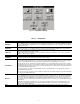
Specifications


3
GENERAL
This publication contains controls, operation, start-up, ser-
vice and troubleshooting information for the 30XW150-400
water-cooled liquid chillers with electronic controls. The
30XW chillers are equipped with ComfortLink controls and
electronic expansion valves. The AquaForce
®
30XW chillers
offer two different user interface devices, the Touch Pilot™
display and the Navigator™ display.
Conventions Used in This Manual — The follow-
ing conventions for discussing configuration points for the
Navigator™ module and Touch Pilot™ display will be used in
this manual.
Point names for the Touch Pilot™ display will be shown in
bold. See Appendix A for a complete list of point names. Item
names for the Navigator™ module will be shown in bold ital-
ics. See Appendix B for the complete path name preceding the
item name. The point and item names in Appendices A and B
will be listed in alphabetical order and the path name for each
will be written with the mode name first, then any sub-modes,
each separated by an arrow symbol ( .
This path name will show the user how to navigate through the
Navigator™ module or the Touch Pilot™ display to reach the de-
sired configuration. The user would scroll through the modes and
sub-modes using the and keys on the Navigator™ dis-
play. For the Touch Pilot™ display, the user would simply touch
the menu item on the screen. The arrow symbol in the path name
represents pressing to move into the next level of the
menu structure for the Navigator™ module, or touching the menu
item on the screen for the Touch Pilot™ display.
When a value is included as part of the point name, it will be
shown after the point name after an equals sign. If the value
represents a configuration setting, an explanation will be
shown in parentheses after the value. The Touch Pilot™ name
will be shown first with the Navigator™ name following. As
an example,
(Staged Loading Sequence = 1, LLCS = Circuit A leads).
Press the and keys simultaneously on
the Navigator™ module to display an expanded text description
of the point name or value. The expanded description is shown in
the Navigator™ display tables (Appendix B) but will not be
shown with the path names in text. The Touch Pilot™ display will
show an expanded description of the point name. To view the ex-
panded point name for the Touch Pilot™ display refer to Appen-
dix A.
The Touch Pilot™ display configures the unit via the CCN
(Carrier Comfort Network
®
) Tables, which are located in Ap-
pendix C of this manual.
Display Module Usage
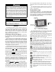
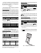
TOUCH PILOT™ DISPLAY — The Touch Pilot™ display
is the standard user interface for the AquaForce 30XW chillers
with the ComfortLink control system. The display includes a
large LCD (liquid crystal display) touch screen for display and
user configuration, a Start/Stop button, and an Alarm Indicator
LED (light-emitting diode). See Fig. 1.
The Touch Pilot™ display can be used to access various
Carrier Comfort Network
®
devices. For operation under these
circumstances, contact your Carrier representative.
Operation of the Touch Pilot™ display is driven from the
displays on the touch screen. The Touch Pilot™ display uses
the following screen “buttons” to allow the user to operate the
display and navigate within and between screens.
“BACK” returns to the next higher screen in the
hierarchy.
“HOME” displays the Default Group Display screen
for Touch Pilot™ display. The Default Screen is a
user-configured display of up to 9 points on each of 8 screens.
This allows for quick access to various, frequently viewed
points, without navigating through the Main Menu structure.
This button is available at all menu levels and returns the user
to the first Default Group Display screen.
“MAIN MENU” displays the Main Menu screen. This
allows access for viewing and configuration, where
possible, of all points supported by the controller. This includes
points such as set point and operational configuration. This
button is available at all menu levels and returns the user to the
Main Menu screen.
“PREVIOUS” moves the user to the next earlier
screen in a group of sequential screens of the same
type.
“NEXT” advances the user to the next screen in a
group of sequential screens of the same type.
“OK” agrees with, or says “yes” to a prompt and per-
forms the appropriate processing.
“NO” rejects, or says “no” to a prompt and performs
the appropriate processing.
“CANCEL” terminates an ongoing action and returns
to the current screen without any other processing.
“CLEAR DATA” clears the data value in a data entry
dialog box. This button is used to clear incorrect data.
“RESET DATA” zeros the data value in a data entry
dialog box.
CAUTION
To prevent potential damage to heat exchanger tubes,
always run fluid through heat exchanger when adding or
removing refrigerant charge. Use appropriate antifreeze
solutions in evaporator and condenser fluid loops to pre-
vent the freezing of heat exchangers or interconnecting pip-
ing when the equipment is exposed to temperatures below
32 F (0° C). Proof of flow switch is factory installed on all
models. Do NOT remove power from this chiller during
winter shut down periods without taking precaution to
remove all water from heat exchangers. Failure to properly
protect the system from freezing may constitute abuse and
may void warranty.
CAUTION
Compressors require specific rotation. Swap any two
incoming power conductors to correct compressor rotation.
Do not change factory-installed power wiring at circuit
breakers, comtactors, or compressors.
ENTER
ESCAPE
ENTER
ALARM
INDICATOR
LIGHT
STA RT-STOP
BUTTON
LCD TOUCH
SCREEN
Fig. 1 — Touch Pilot™ Display
a30-4456 (b&w)