
Instruction manual


6
R
G
C
E
L
O
Y
THERMOSTAT
R
R
C
O
Y
G
C
W
2
W
2
W
2
W
3
E
ODTS
FAN COIL
HEAT PUMP
(CONTROL)
RED
GRY
BRN
WHT
VIO
BLU
A09386
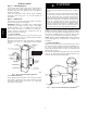
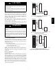
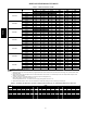
Fig. 12 -- Wiring Layout Heat Pump Unit
(Cooling and 2 -- Stage Heat with 1 Outdoor Thermostat)
R
G
C
L
E
O
C147C963
Y
THERMOSTAT
R
R
C
O
Y
G
C
W
2
W
2
W
2
W
3
E
FAN COIL
EMERGENCY HEAT RELAY
HEAT PUMP
(CONTROL)
ODTS1
ODTS2
RED
GRY
BRN
WHT
BLU
VIO
A09387
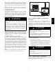
Fig. 13 -- Wiring Layout Heat Pump Unit (Cooling and
2-- Stage Heat with 2 Outdoor Thermostats)
R
E
W
2
R
C
THERMOSTAT
FAN COIL
HEAT PUMP
(CONTROL)
G
C
W
2
E
L
G
C
R
O
Y
ODTS
O
Y
W
3
W
2
A09388
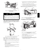
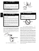
Fig. 14 -- Wiring Layout Heat Pump Unit
(Cooling and 2 -- Stage Heat for Manufactured Housing)
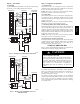
Transformer Information
Transformer is factory--wired for 230v operation. For 208v
applications, disconnect the black wire from the 230v terminal on
transformer and connect it to the 208v terminal. (See Fig. 15.)
230
C
208
BRN
RED
YEL
BLK
SECONDARY
PRIMAR
Y
A05182
Fig. 15 -- Transformer Connections
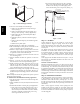
Heater Staging
PROPERTY DAMAGE HAZARD
Failure to follow this caution may result in product or
property damage.
If W2, W3, and E on any 3 stage heater (18, 20, 24, or
30kW) are individually connected as with outdoor
thermostats or any other situation, emergency heat relay must
be used. This relay is in kit Part No. KHOT0201SEC and is
normally used with kit Part No. KHAOT0301FST for 2
outdoor thermostat systems.
CAUTION
!
The controls are factory circuited for single--stage operation. For
2-- stage operation, use outdoor thermostat kit Part No.
KHAOT0301FST, and for 3--stage use both kits Part No.
KHAOT0201SEC and KHAOT0301FST.
FX4D