
Instruction manual


7
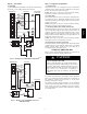
When 2 stages are desired, cut W3 at the W2 wire nut, strip and
reconnect per the thermostat kit instruction. (See Fig. 12.) When 3
stages are desired, cut the W2 wire nut off and discard. Strip W2,
W3, and E and reconnect per thermostat kit instructions. (See Fig.
13.)
NOTE: When 3 stages are used or anytime the E terminal is not
tied to W2, the emergency heat relay, part of outdoor kit Part No.
KHAOT0201SEC must be used.
C. Manufactured Housing
In manufactured housing applications, the Code of Federal
Regulations, Title 24, Chapter XX, Part 3280.714 requires that
supplemental electric heat be locked out at outdoor temperatures
above 40_F(4_C), except for a heat pump defrost cycle. Refer to
Fig. 14 for typical low voltage wiring with outdoor thermostat.
D. Ground Connections
ELECTRICAL SHOCK HAZARD
Failure to follow this warning could result in personal injury
or death.
According to NEC, ANSI/NFPA 70, and local codes, the
cabinet must have an uninterrupted or unbroken ground to
minimize personal injury if an electrical fault should occur.
The ground may consist of electrical wire or metal conduit
when installed in accordance with existing electrical codes. If
conduit connection uses reducing washers, a separate ground
wire must be used.
!
WARNING
NOTE: Use UL--listed conduit and conduit connector for
connecting supply wire(s) to unit to obtain proper grounding.
Grounding may also be accomplished by using grounding lugs
provided in control box.
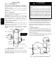
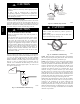
E. Minimum CFM and Motor Speed Selection
Units with or without electric heaters require a minimum CFM.
Refer to the unit wiring label to ensure that the fan speed selected is
not lower than the minimum fan speed indicated. Fan speed is
selected at the motor. To change motor speeds disconnect the blue
fan lead from terminal two and move to desired speed tap; low
(one), medium (two), and high (three). Speed taps one, two and
three have a 90 second blower time delay pre--programmed into the
motor. Speed tap (four) is used for electric heat only (with 0 second
blower time delay) and the white wire must remain on tap four.
Speed tap (five) is the same CFM as speed tap three, but has a 0
second blower time delay pre--programmed into the motor (see
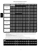
Airflow Performance Table 1 for actual CFM for each tap). See
Fig. 16.
NOTE: In low static applications, lower motor speed tap should
be used to reduce possibility of water being blown off coil.
1 2 3 4 5
A09390
Fig. 16 -- Motor Speed Selection
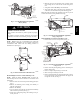
Step 5 — Refrigerant Tubing Connection and
Evacuation
Use accessory tubing package or field--supplied tubing of
refrigerant grade. Suction tube must be insulated. Do not use
damaged, dirty, or contaminated tubing because it may plug
refrigerant flow--control device. ALWAYS evacuate the coil and
field--supplied tubing to 500 microns before opening outdoor unit
service valves.
PRODUCT DAMAGE HAZARD
Failure to follow this caution may result in product or
property damage.
A brazing shield MUST be used when tubing sets are being
brazed to the unit connections to prevent damage to the unit
surface and condensate pan fitting caps.
CAUTION
!
Units have sweat suction and liquid tube connections. Make
suction tube connection first.
1. Cut tubing to correct length.
2. Insert tube into sweat connection on unit until it bottoms.
3. Braze connection using silver bearing or non--silver bearing
brazing materials. Do not use solder (materials which melt
below 800_F / 427_C). Consult local code requirements.
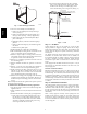
4. Evacuate coil and tubing system to 500 microns using deep
vacuum method.
PRODUCT DAMAGE HAZARD
Failure to follow this caution may result in product or
property damage.
Wrap a wet cloth around rear of fitting to prevent damage to
TXV and factory--made joints.
CAUTION
!
Step 6 — Refrigerant Flow--Control Device
The FX4D is equipped with PuronR refrigerant TXV. Use outdoor
units designed for PuronR refrigerant only.
FX4D