
Owner's manual


4
IOM-1465
11. Apply an appropriate lubricant to the threads
of the spring chamber (2). Reverse Steps
B.2 and B.3 to complete assembly. Tighten
spring cham ber (2) to body (1) with a 30-35
Ft-lbs torque value.
12. Pressurize with air and spray with liquid leak
detector to test around body (1) and spring
cham ber (2) for leak age. En sure that an outlet
pressure is main tained dur ing this leak test of
at least mid-range spring level; i.e. 125-200
psig (8.6-13.8 Barg) range spring, 163 psig
(11.2 Barg) test pres sure min i mum.
C. Trim Inspection:
1. Trim inspection requires that the diaphragm(s)
be re moved. Refer to pre vi ous procedure
Sec tion VI.B, steps 1 through 7.
2. Remove body (1) from vise and secure a
screwdriver, tool end up, in vise. Set body (1)
so as to engage screwdriver into slotted end of
the plug (3) from the body (1) inlet con nec tion
and hold fi rm.
3. Remove pusher plate (6). Looking down into
the body (1) cavity, use a slotted tool to push
down on the spring seat (5) and slip sideways
to dis en gage (through slot) from plug (3).
4. Remove spring seat (5) and plug spring (4).
5. Grasp plug (3) while carefully lifting body (1).
Remove plug (3) from body (1) inlet, taking
care not to allow plug (3) to drop out.
6. Inspect integral seat in body (1). If seat shows
erosion or wear, re place regulator.
7. Clean debris from within body (1) cavity.
Clean parts to be reused according to owner's
1. Erratic operation; chattering.
pro ce dures. NOTE: On reg u la tors originally
sup plied as "oxygen clean", Op tion 1465-55
main te nance must in clude a level of clean li-
ness equal to Cashco's clean ing spec. #S-
1134. Contact factory for details.
8. Inspect spring seat (5), plug spring (4) and
plug (3). If worn, nicked or depressed, re place
regulator.
9. Lap plug (3) with lapping compound by in-
sert ing it back up into the body (1) inlet and
hold fi rm. Engage a screwdriver into the slotted
end of the plug (3) from the body (1) inlet and
rotate plug (1) back and forth in a circular mo-
tion. Do not overlap. Clean lapping com pound
on plug (3) and in body (1).
10. Reverse steps 1 through 5 for reassembly.
NOTE: When reassembling plug (3), plug
spring (4), and spring seat (5), be sure that
this "assembly" is centered into the body (1)
cav i ty to ensure proper seating of plug (3).
Apply an appropriate lubricant to the threads
of the spring chamber (2). Tighten spring
cham ber (2) to body (1) with a 30-35 Ft-lbs
torque value.
11. Bench test unit for suitable operation. NOTE:
Reg u la tors are not tight shut off devices.
Even if pres sure builds up beyond setpoint,
a reg u la tor may or may not de vel op bubble
tight shut off.
12. Pressurize with air and spray with liquid leak
detector to test around body (1) and spring
cham ber (2) for leakage. Ensure that an outlet
pressure is main tained during this leak test of
at least mid-range spring level; i.e. 125-200
psig (8.6-13.8 Barg) range spring, 163 psig
(11.2 Barg) test pres sure minimum.
SECTION VII
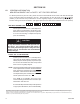
VII. TROUBLE SHOOTING GUIDE
Possible Causes Remedies
A. Oversized regulator; inadequate
rangeability.
A1. Check actual fl ow conditions, re-size regulator for minimum and
maximum fl ow.
A2. Increase fl ow rate.
A3. Decrease regulator pressure drop; decrease inlet pressure by
placng a throttling orifi ce in inlet piping union.
A4. Install next step higher range spring. Contact factory.
A5. Before replacing regulator, contact factory.
B. Cavitation B. Use multiple 1465's in series to stage the pressure drops. Refer
to 1465 Technical Bulletin for water cavitation chart.