(without price) Pocket PC EG-800 (JX-590A) SEP.
CONTENTS 1. MAIN FEATURES ---------------------------------------------------------------------------------- 1 2. SPECIFICATIONS ---------------------------------------------------------------------------------- 2 3. UNPACKING 3-1. Optional Parts and Accessories which can be supplied as the spare parts --------- 4 3-2. The other significant Optional Parts and Accessories --------------------------- 4 4. GENERAL GUIDE and INITIAL SETUP 4-1.
15. PARTS LIST ---------------------------------------------------------------------------------------- 75 16. EXPLODED VIEW 16-1. PC Board Assembly and COMPONENTS ------------------------------------------- 78 16-2. PCB ASSY/MAIN ----------------------------------------------------------------------------- 79 16-3. PCB ASSY/KEY ------------------------------------------------------------------------------ 80 16-4.
1. MAIN FEATURES Visit the following CASIO Tokyo Web site whenever you want to obtain the information (Main Features, Specifications so on) and the software concerning CASIO overseas products. Address(URL): http://www.casio.co.jp/English/ Visiting this home page, you will see the screen display as shown to the right. You can select CASIO overseas products genre using this page. Select Business Solution concerning EG-800.
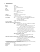
2. SPECIFICATIONS Model: Display: EG-800 240 × 320 dots TFT Color LCD (65,536 colors) CPU: VR4122 Memory: 32MB Interfaces: Serial: RS-232C, 115.2 kbps max. Infrared: IrDA Ver. 1.1 Range: 30 cm max. USB (Client) Card Slot: CompactFlash card, 3.3V Type I/ Type II Headphone jack: ø 3.
Current consumption: Note: 1. When measuring these current, it is recommended to use the analog ammeter to make the measurement easier due to protecting the ammeter from noises. 2. Make LCD display contrast suitable (default) condition before measurement. 3. Measure under the ambient temperature range 15˚C~35˚C Operation Mode Input Voltage Current Consumption Main Menu of OPERATION CHECK in this manual Rechargeable Battery : 4.0 ± 0.
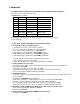
3. UNPACKING 3-1. Optional Parts and Accessories which can be supplied as the spare parts Some parts can be supplied as spare parts. Its PARTS LIST is as follows; Item Code No.
—5—
Refer to the following web site Home page concerning below optional parts and Accessories (6~10). URL- http://www.casio.co.jp/English/ce URL- http://www.casio.co.jp/English/system/pa/products/ht/eg800.html 6. CF camera card This digital Camera Card allows EG-800 unit user to take still or movies and send them to their home or office instantly. Model Name: JK-710DC 7. Stereo Earphone with Remote Control For use with music, reading E-mail and E-book with the remote control. Model Name: JK-840HE 8.
4. GENERAL GUIDE and INITIAL SET UP 4.1. General Guide Charge indicator (Amber/Green) Lights amber when the battery pack is charging and turns green when full charge is achieved. Power button Turns power on and off. Indicator lamp (Red) Alerts you to alarms and warning. Microphone Card slot cover Start button (Program button) Press to display the Start menu. Stylus Action control See “About the [Action] Control” on the next page.
Battery lock RESET button Card lock switch If the inserted card has a lock, this switch locks the card in place so it does not come out accidentally. Main battery (rechargeable battery pack) About the [Action] Control Operations can be performed by pressing and rotating the [Action] control. Rotating the [Action] control performs operations similar to the up and down arrow keys of a computer keyboard. Pressing the [Action] control performs an operation similar to the Enter key of a computer keyboard.
Attaching the Strap Attach the strap to the CASSIOPEIA a shown in the illustration below. 1. Attach the card slot cover to the CASSIOPEIA. 2. Pass the strap loop through the strap hole and then pass the other end of the strap through the loop as shown below. Important • Use only the strap that comes with your CASSIOPEIA. • Never swing the CASSIOPEIA around by its strap.
3. Insert the left and right edges of the touch screen sheet into the slits between the touch screen and the unit's case. • Dust or dirt between the sheet and the touch screen can scratch the touch screen. Take care to make sure that no foreign matter gets between the sheet and touch screen when affixing the sheet. Using the Stylus Data input and virtually all other operations are performed using a stylus, which is housed inside the stylus holder in the higher right corner of the CASSIOPEIA.
Adjusting Display Contrast Perform the following operations to adjust display contrast and make figures on the display darker or lighter. • Tap and then Settings. On the System tab, tap Brightness. Follow the instructions on your screen for adjusting the contrast. • You can also adjust contrast by holding down [Action] and pressing the top of the cursor button to make contrast darker, and the bottom of the cursor button to make it lighter.
Main Battery and Backup Battery Your CASSIOPEIA uses two types of batteries for power: a rechargeable user-replaceable rechargeable battery pack for the main battery, and a button type lithium battery for memory backup. • We recommend that you use the Power Properties to keep informed about the current levels of your main and backup batteries. See the separate Pocket PC User’s Guide and Pocket PC online help for more information about this properties.
• Use only the types of batteries specified for use with this unit. • Charge the battery pack in an area where the temperature is between 10˚C (50˚F) and 35˚C (95˚F). Charging in areas that are very cold or exposed to direct sunlight can cause deterioration and leaking of the battery pack. • To avoid deterioration and leaking, the battery pack is designed to discharge even when you do not use the CASSIOPEIA.
NOTE Type I CF Card is different from Type II CF Card with thickness and configuration as shown below. * Length and Width of Type I are the same as ones of Type II.
1. Make sure your CASSIOPEIA is turned off. • Press the [Power] button to turn off power. 2. Remove the card slot cover from the CASSIOPEIA. • Slide the card release to the Free position. 3. If there is already a card in the slot, use the stylus to pres the EJECT button straight down, and remove the card. EJECT button 4. Slide the card you want to use into the card slot. • Make sure the top of the card is facing towards the top of the CASSIOPEIA unit.
Using Peripherals This section explains use of the various peripherals that are available for use with the CASSIOPEIA. Using the AC Adapter (AC adapter + AC power cord) You can use the AC adapter to directly power the CASSIOPEIA or to supply power through the cradle. The battery pack charges while the CASSIOPEIA is directly connected to a power source by the AC adapter or while it is on the cradle.
Using the AC Adapter/Charger (CH-C59200U) As its name suggests, the AC Adapter/Charger functions as both a charger for the battery pack and as an AC adapter. ■ To charge a battery pack mounted on the AC adapter/charger 1. Plug the AC adapter/charger into a wall outlet as shown in the illustration. AC power cord 2. Mount the battery pack onto the AC adapter/charger. EJECT switch Chargeable battery pack RAPID CHARGE indicator Lights red while rapid charging is in progress.
3. After charging is complete, slide the EJECT switch in the direction indicated by the arrow and remove the battery pack from the AC adapter/charger. EJECT switch Important • Unplug the AC cord from the wall outlet when you are not using the AC adapter/charger. • If the indicator goes out during charging (indicating a charge error) or if a full charge is not achieved within a preset amount of time, unplug the adapter/charger from the wall outlet and stop charging.
Using the Cradle The cradle provides quick and easy connection between your CASSIOPEIA and a personal computer. Data passes between the CASSIOPEIA and cradle over a non-contact infrared link. CASSiOPEIA can also be powered from an AC power source when it is placed on the cradle. Connecting the Cradle to a Computer You can connect the cradle to a computer using either a serial cable or the USB cable. Important • Do not have the serial cable and USB cable connected to the cradle at the same time.
■ To connect using a 16-pin serial cable Important Bc sure to turn off the CASSIOPEIA and your computer before connecting the cradle. 1. Slide the cradle's serial/USB port cover so the serial port is open. 2. Connect as illustrated below. AC adapter Cradle Serial port Serial cable Note • You can use the above configuration to connect directly to a computer's 9-pin serial port. If your computer has a 25-pin serial port, you will need to purchase a commercially available connector (9pin to 25-in).
■ Mounting the CASSIOPEIA Onto the Cradle Important Make sure that CASSIOPEIA power is turned off before you place it onto or remove it from the cradle. Use the following procedure to place the unit onto the cradle. 1. Place the cradle on a desk or other flat, level surface. 2. Turn off the CASSIOPEIA. 3. Place the CASSIOPEIA onto the cradle as shown in the illustration. 4. Orient the CASSIOPEIA in relation to the cradle as shown in the illustration below.
Using the Serial Cable (20-pin) You can use the serial cable to connect the CASSIOPEIA directly to your computer. Important • See "Required System Configuration" on the later page for the computer system that is required for direct serial connection. • Be sure to turn off the CASSIOPEIA and your computer before connecting the CASSIOPEIA. • The illustration below is just one possible connection configuration. The location and layout of serial ports vary from computer to computer.
To connect to a computer using the CASSIOPEIA USB cable 1. Plug the USB cable into the USB port of your computer. 2. Turn off your CASSIOPEIA. 3. Connect the other end of the USB cable to your CASSIOPEIA. USB port CASSIOPEIA USB cable Digital Phone Connection Cable • U.S. and Canada: Use a cdma digital phone connection cable (JK-541CA). • For a GSM type digital phone, use a commercially available cable that is compatible with the CASSIOPEIA connector.
Important • Make sure your CASSIOPEIA is turned off before connecting the digital telephone cable. • See the Pocket PC User's Guide for information about settings, operations, and precautions when connecting to a company network or the Internet. • Make sure you are in an area where your telephone signal is strong before trying to dial in to a computer.
Windows Media Player for Pocket PC Use Windows Media Player for Pocket PC to listen to digital audio files. To switch to Windows Media Player, tap and then Windows Media Player. Using Windows Media Manager for Pocket PC Use Windows Media Manager for Pocket PC on the desktop computer to create digital audio files in Windows Media format and to transfer audio content to your Pocket PC or storage card.
What is Packaged Content? Packaged content is digital music that has been encrypted for distribution to prevent unauthorized access to copyrighted content. Windows Media Player for Pocket PC cannot play packaged content without a valid license. First use Windows Media Player on the desktop computer to obtain packaged content that has a license that allows transferring the content to your Pocket PC.
5. Follow the steps in the Welcome Wizard. 6. When finished, you’ll see the Today screen. • See “Pocket PC Basics” at the back of Quick Start Guide for information about the Today screen and other Pocket PC Basics. • You also need to install ActiveSync before you can communicate with a desktop computer. Important • If the touch panel does not respond when you tap it or if nothing appears on the display, try performing a full reset.
5. RESET OPERATION and BATTERY REPLACEMENT 5-1. Reset Operation and FULL RESET Resetting the Unit “Reset” is similar to a computer reboot. Performing a reset deletes any data that is in the process of being input or edited, without yet being saved. Data stored in memory and all settings, however, are retained. Perform the reset operation whenever the unit fails to operate correctly due to operational error or some other abnormality. Either of the following symptoms indicates that reset is required.
See the User’s Guide for details about initializing memory.” This message indicates that the memory error is fatal and so recovery is impossible. Press the [Action] control to execute a full reset (memory initialize), which deletes all data stored in memory. • Pressing the [Action] control should display the Startup screen followed by the touch screen calibration screen. The remainder of this procedure indentical to the Initial Setup described in the Quick Start Guide.
4. Press the [Action] control again. • This starts the full reset operation, which deletes all data in memory. • Pressing the [Action] control displays the Startup screen. The remainder of this procedure identical to the Initial Setup described in the Quick Start Guide. Perform the steps of the Initial Setup procedure. You can abort the full reset operation while the messages in steps 2 and 3 are on the display by pressing the [Record] button.
Memory Backup Lithium Battery Replacement User can not replace the memory backup battery as described in MAIN FEATURES. This Lithium battery is assembled onto Key PC Board Assembly by soldering as shown below. Therefore, to remove or assemble this battery, use a soldering iron. Replace this battery referring to DISASSEMBLY PROCEDURE, PARTS LIST and EXPLODED VIEW in this manual.When replacing, slide SW10 to OFF position. Refer to page 80 and PCB VIEW in this manual.
6. DATA COMMUNICATIONS 6-1. General Performing Initial Setup and FULL RESET, data saved in the unit will be deleted. Performing MEMORY BACKUP/RESTORE and CARD BACKUP TOOL Operations descibed in this Chapter, save these data to PC and CF card before performing iInitial Setup and FULL RESET. The following data communications are mainly applicable to E-125. 1. Between PC and EG-800 using Activesync 3.1 software 2. Between CF card and EG-800 3. Between Mobile phone and EG-800 4. Between two units using IrDA 5.
Requirements for Microsoft Outlook ® 2000 Microsoft Outlook 2000 requires 153 MB of disk space for a full installation. 24 MB system RAM recommended. Important • When installing ActiveSync on a computer, check to make sure that the specified COM port number correctly indicates the serial port to which the cradle is connected. • Some laptop and sub-compact computers with built-in infrared ports and modems are initially configured so the COM port is not always used as a serial port.
Copyright Notice No part of this publication may be reproduce, transmitted, transcribed, stored in a retrieval system, or translated into any human or computer language, in any form or by any means, without the express written permission of CASIO COMPUTER CO., LTD. Copyright 2000 CASIO COMPUTER CO., LTD. All rights reserved. ■ Introduction Card Backup Tool lets you quickly and easily back up your CASSIOPEIA memory data to a memory card.
• Do not perform any button or screen operations on the CASSIOPEIA while a backup or restore operation is in progress. Do not touch the CASSIOPEIA at all until the backup or restore operation is complete. • Files and other data are automatically compressed before being stored in CASSIOPEIA memory. Make sure the memory card you are using for backup has enough unused space to store the data. Backing Up Data Use the following procedure to back up data.
5. Tap Backup now. • This causes the dialog shown below to appear. • If you do not wish to assign a password, go to step 6 without inputting anything. 6. Tap Yes to start the backup or No to close the dialog without backing up anything. • The "Backup in Progress" dialog appears while the backup operation is being performed. • The message "Backup complete!" appears on the display after the backup operation is complete. 7. After backup is complete, tap OK to quit Card Backup Tool.
• To return CASSIOPEIA to the exact status it was when you backed up the data, perform a full reset before restoring the data. See the separate Hardware Manual for information about the full reset. Use the following procedure to restore data. Make sure you read the precautions under "Read this first!" on the previous page before starting. To restore data 1. Connect the AC adapter to your CASSIOPEIA. 2. Reset the CASSIOPEIA. 3.
Deleting a Backup File You can use the following procedure to delete the backup files you created using Card Backup Tool. Delete a file when you no longer need it, when you want to free up space on a memory card, etc. To delete a backup file 1. Insert the memory card that contains the backup file you want to delete into the CompactFlash Card slot of the CASSIOPEIA. 2. Tap , Programs, Utility, and then Card Backup. • This starts up Card Backup Tool. 3. Tap Backup File Delete.
6-6. Mobile communication Refer to page 23 in this manual. Supports WAP, SMS, E-mail and Internet when used in combination with a GSM mobile phone. MTDS Web Site *Internet access requires an account with an Internet service provider. note Communication systems differ from country-to-country. Contact your local CASIO retailer for full details about communications that are supported in your area.
6-7. Infrared Communication Transfer Items Using Infrared Using infrared (IR), you can send and receive information, such as contacts and appointments, between two Windows-powered Pocket PCs. To send information 1. Switch to the program where you created the item you want to send and locate the item in the list. If you want to send more than one item, drag the stylus across the items you want to send. 2. Align the IR ports so that they are unobstructed and within a close range.
7. ADUSTMENT There are two kinds of adjustments concerning EG-800. Refer to 8-4-2-7. Color Bar Check (including a display adjustment) and 8-4-2-8. Setting (Adjusting) DC voltage to AD converter in OPERATION CHECK in this mamual.
8. OPERATION CHECK 8-1. Preparation 1. EG-800 (Prepare another units to perform IrDA communication check except the checking unit.) 2. Compact Flash Memory Card 3. Rechargeable battery pack JK-210RBM etc. (Refer to UNPACKING.) 4. AC adapter (AD-C59200U), or both AC adapter (AD-C59200G) and AC power cord (CBL-K799AC-EU etc.) (Refer to UNPACKING.) 5. Cradle with RS-232C Cable JK-550CR (Refer to UNPACKING.) 6. PC installed ActiveSync 3.1 7. Diagnostic program files for EG-800 : diag.exe and diagboot.
8. After this procedure is completed, the display shown to the right appears. 9. After clicking Explore icon in the right dialog box, click My Pocket PC icon. 10. Doing so, Storage Card holder icon will appears. "Storage Card" holder indicates CF card. If CF card is not inserted into the slot, this holder will not appear. 11. After clicking this icon, make a new holder named jx590diag. 12. Make a new holder named casioconfidential in jx590diag holder. Perform these spellings precisely.
8-2-2. Direct Installation in Only D-RAM in the unit without CF card Using the following procedure, you can directly install the diagnostic program in D-RAM in the unit without CF card. 1. Perform 2~9 in the procedure of 8-2-1. 2. Clicking Windows holder in ActiveSync 3.1 program, open this holder. 3. Enter both CASIO_JXdiag.exe and diagboot.exe files into this holder. 4. Doing so, the installation of the diagnostic program to D-RAM in the unit starts automatically.
8-4. Operation Check 8-4-1. How to enter into Operation Check Mode It is recommended to perform FULL RESET with the unit to delete the data saved in D-RAM before this check. To enter into this check Mode, perform the operation described in item 18 of 8-2-1 or item 7 of 8-2-2 after installation of diagnostic program. Or, after the installation of diagnostic program by 8-2-1, press Contacts button over 3 seconds while holding down Power button until below Operation Check Main Menu appears.
8-4-2-2. Touch Panel Check 1. Tapping above 2 TOUCH PANEL on the screen using a stylus, the following Touch Panel Check Menu appears. ** Touch Panel ** 1 Case 2 Points 3 Cross 2. Tapping 1 Case, "Case ----→ OK" display appears. Pressing Action Control button, display Touch Panel Check Menu again. Generally speaking, pressing Action Control button, prior Menu or Display can be recovered during Operation Check. 3. Tapping 2 Points, four cross marks appears near four corners in the screen.
4. Tapping 4 RAM TEST, the following display appears. The other displays may appear. ** RAM CHECK ** - RAM CHK OK Pressing Action Control button, Memory Check Menu display appears again. 5. Tapping 6 RAM R/W TEST, the following display appears. ** RAM CHECK ** - RAM DATA WRITE Write ... end ActionKey PUSH! 6. Pressing Action Control button according to above message, the following display appears. ** RAM CHECK ** - RAM DATA WRITE Write ...
5. Tapping another unit's screen, the following display appears. Ready Ready OK Ready On the other hand, the following display appears with checking unit. Ready OK Ready Ready 6. Pressing Action button with both units, Serial port Check Menu display appears again. 7. Tapping 7 Send / Receive with both unit, the following display appears. 1 Send data (4Mbps) 2 Receive data (4Mbps) 8.
8-4-2-6. Others Check 1. Tapping 7 Others, the following Others check Menu display appears. ** Others ** 1 Switch 2 Keyboard RAMDOM 3 Disp Loop 4 BackLight 5 Compact Flash (CDs, CDOR) 2. Tapping 1 Switch, the following display appears and Red light is flickered from the right LED. For example, VDET1B OFF VDET2 OFF VDET3 OFF VDETS OFF VDETCF OFF AC Adapter USED Cover CLOSED Charge ON Ir WakeUP OFF AD Remocon OFF Audio Jack OFF 3. Removing the rechargeable battery, COVER will become OPEN.
8-4-2-7. Color Bar Check (including a display adjustment) 1. Tapping 8 COLOR BAR, the following Color Bar check Menu display appears. ** COLOR BAR ** 1 Contrast 2 Scroll 3 GRAY 2. Tapping 1 Contrast, the following color bar display appears. RED GREEN BLUE BLACK WHITE Pressing Action Control button, Color Bar check Menu display appears again. Even if tapping 2 Scroll, this unnecessary check can not be performed because this check becomes unnecessary. 3. Tapping 3 GRAY, all gray display appears on the screen.
8-4-2-8. Setting (Adjusting) DC voltage to AD converter The following operation are not only for Check, but also for setting (adjusting) for DC voltage to AD converter in CPU. When calibration for touch panel, battery voltage detection and so on are not correctly performed, try to check and perform these settings (adjustments). Prepare one DC voltage stabilizers for Main battery power supply. Important These settings (adjustments) for the main PC Board Assembly has not be performed in the factory.
Voltage Write-> Contacts Key Escape -> ON Key If the unit can not read the voltage 4.2V correctly, "No Good. Please retry!!" message will appear. Note that the unit can not be progressed in the next stage whenever this message appears. 8. Make the voltage power supply added to the main battery terminal 3.7V ± 0.05V. Then, press Contacts button again. Doing so, the following display appears. *** *** AD Value Read! 0x8... AD Value Read! 0x8...
9. TROUBLE SHOOTING Before assuming malfunction and contacting your service provider when experiencing operational problems, be sure to check the following information as well as the troubleshooting section of the Pocket PC User’s Guide first. Response to screen tap is exceedingly slow. Possible Cause Recommended Action Available memory is very low. Reset the unit. If resetting the unit does not correct the problem, perform a full reset (which deletes memory contents).
Nothing happens when the touch screen is touched. Possible Cause Recommended Action The touch screen is out of calibration. Recalibrating the touch screen. Static electricity or some other problem has caused the touch screen to malfunction. Reset the unit. The touch screen is damaged. Contact your original dealer or an expert. The screen is locked up. Possible Cause Recommended Action Internal malfunction Reset the unit.
10. CIRCUIT BLOCK DIAGRAM Timer clock 32.768kHz OSB System clock for CPU 18.432MHz PLL 150MHz KEYS CORE of CPU Action/ Voice etc. VSUB Bus Control Unit Alarm LED (RED) LED IF (Key PCB) Rechargeable Battery IC200 Power IC * Power supply * Voltage regulator * Voltage detection * Charge control General Purpose Interface Instruction/ Cache Mem.
11.
12. SCHEMATIC DIAGRAMS 12-1.
12-1. Main block (2/3) TYP-15.
12-1.
12-2.
12-3.
12-4 Jack block — 62 —
12-5.
12-6 Sub block — 64 —
13.
— 66 —
— 67 —
Key PC Board — 68 —
14. DISASSEMBLY PROCEDURE Refer to GENERAL GUIDE, PARTS LIST and EXPLODED VIEW in this manual. 1. Remove the stylus as shown to the right. 2. Rotate the eject switch counterclockwise using a coin or a screwdriver to remove the lithium polymer rechargeable battery (main battery) as shown to the right. 3. Remove the main battery and card slot cover as shown to the right.
4. Remove the six screws assembled onto the back as shown to the right. Note that below two screws are longer compared with the upper four screws in the right photograph. Removing these screws, the unit can be opened. 5. Open the unit as shown to the right. The unit can be opened by hand. In other words, the unit can be opened without an opener or the other tools. 6. Disconnect the flat cables from connectors assembled onto the man PC Board Assembly.
In case of CN1, CN8, CN10 and CN11 (except CN9): pull this tag flat cable pull out the flat cable After pulling above tag, pull out the flat cable as shown above. In case of CN9: pull this tag CN9 Main PC Board flat cable pull out the flat cable After pulling the tag upward, pull out the flat cable as shown above.
■ Disassembling the lower case assembly 7. Remove screws assembled onto the lower case assembly as shown to the right. Doing so, the main PC Board can be removed including the jack PC Board assembly. 8. After disconnecting the flat cable from CN6 connector, remove the main PC Board assembly as shown to the right. Refer to PCB ASSY/MAIN in EXPLODED VIEW in this manual concerning CN6 position.
■ Disassembling the upper case assembly 9. Remove the four screws as shown to the right. 10. Remove the inner case unit onto which TFT LCD Module and a Touch screen panel are assembled as shown to the right.
11. After removing screws, remove the touch screen panel assembly as shown to the right. 12. Remove TFT LCD Module as shown to the right. Note that TFT LCD Module strongly attaches to the inner case by the adhesive tape. Refer to EXPLODED VIEW in this manual concerning these adhesive tape positions. When peeling this module, don't use the chemical substances. Doing so will damages to this module.
PARTS PRICE LIST EG-800 N N N N N N N N N N N Item Code No.
N N N N N N N N N Item Code No.
N Item Code No. Parts Name COMPONENTS N 63 1003 9693 PCB ASSY/MAIN N 65 1003 9695 PCB ASSY/ROM N 66 1003 8406 PLATE 67 1001 1952 COVER 68 1001 1953 PEN SUB ASSY N 69 1003 8407 COVER N 70 1003 9696 CF CAP ASSY 71 1001 1988 FILTER/IRDA SCREWS 100 6394 6400 SCREW 101 6336 8250 SCREW 102 6337 9150 SCREW 103 1003 8146 SCREW 104 6396 7660 SCREW 105 6337 9150 SCREW 106 6338 8270 SCREW 107 6562 1390 SCREW 108 6338 8270 SCREW * Item 108 screw is the same as item 106 screw.
16. EXPLODED VIEW 16-1.
16-2.
16-3.
16-4.
16-4.
16-5.
16-6.
16-7.
CASIO TECHNO CO.,LTD. Overseas Service Division Nishi-Shinjuku Kimuraya Bldg.