
Specifications


SLAA137A
10 MSP430 Internet Connectivity
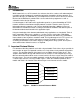
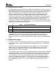
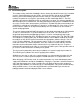
Figure 4. Prototype Board With Components Installed
Appendix A shows the schematic and Appendix B provides a list of components that are needed
to build the module. For each of the discrete parts, there are several manufacturers available.
3.3 Connection to the Network
The CS8900A includes an integrated 10Base-T transceiver. It contains all the analog and digital
circuitry needed for implementing the LAN interface by the use of a simple isolation transformer
(IND1). Similar devices can substitute for this part, but attention must be paid to the voltage turn
ratio between the primary and secondary windings. For 3.3-V operation, this must be 1:2.5 for
the transmission lines and 1:1 for the receive lines. The resistor R1 is used to terminate the
receive lines and the resistors R2 and R3 in series with the transmit lines are used for
impedance matching. The capacitors on the LAN side of the isolation transformer (C24, C25)
can be optionally populated if a shielded RJ45 connector is used. In this case, the signal GNDA
must be connected to the case shield. See Reference [9] for more background information.
A standard RJ45 patch cable can be used to connect the module to either a 10-Mbps or 100-
Mbps hub. A 100-Mbps hub automatically switches down its transfer speed to 10 Mbps if it
detects the CS8900A running at 10 Mbps.