
Specifications


SLAA137A
MSP430 Internet Connectivity 9
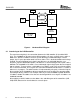
3.2 Circuit Description
The analog circuitry around the CS8900A is built as further described in Resource [8]. A 20-MHz
crystal is connected between the pins XTAL1 (pin 97) and XTAL2 (pin 98) of the CS8900A.
Because of the built-in loading capacitance on the XTAL pins, no external capacitors are
needed. The power-on reset signal is generated by the R/C combination R9/C17. The LAN
controller, other than the MSP430, needs an active-high reset signal. The ethernet controller has
different outputs pins to control LEDs. Pin 100 (LANLED) goes low when the CS8900A transmits
or receives a frame and is connected to a red LED (D1). A yellow LED (D2) connected to pin 99
(LINKLED) is switched on if valid 10Base-T link pulses are detected. The same circuit as well as
the bus interface shown can be implemented directly on a user PCB that can also contain a
special analog application.
The circuitry connected to MSP430F149 contains the described connection to the LAN controller
as well as a JTAG interface, a crystal oscillator and a reset circuit. The JTAG interface is
designed for programming and debugging purposes. It can be used to directly connect the
MSP430 flash emulation tool (FET). All required signals (for example TCK, TDI, TDO/TDI, TMS)
are available at a 14-pin header (X6). An RS232 interface can be added if needed, for example
to establish an SLIP or PPP Internet connection after appropriate software changes. You can
use the TI device MAX3221. This part operates from a single 3.3-V supply voltage and only
needs four small 0.1 µF external capacitors. It has one serial line receiver and one serial line
transmitter and also low-power features which make it very suitable for this task. To get the
maximum MCU performance possible, it is sourced by an 8-MHz crystal. Two capacitors with 15
pF each are used to connect the oscillator pins to ground.
The circuit can be powered by connecting an adequate 3.3-V power supply to pin header X3.
The LED D4 (green) indicates the correct supplying of the module.
All MCU pins not used, as well as the supply potentials, are connected to pin headers X3 and
X4. They can be used for expansion purposes to build and attach a user application circuit.
When designing a PCB for the circuit, be certain to provide a very clean and adequate power
supply to the MSP430 as well to the CS8900A by using bypass capacitors situated next to these
chips and short copper traces. Also especially take care about the design of the analog part
around the LAN controller (use Reference [9] as a detailed guide). For reasons of better routing
ability and EMI reasons, use of a four-layered board is recommended. Figure 4 shows the
prototype board used for developing the Web server software.