(without price) QV-5500SX (KX-712) MAR. 1999 INDEX R Ver.
CONTENTS SPECIFICATIONS ....................................................................................................................................... 1 BLOCK DIAGRAM ...................................................................................................................................... 3 ADJUSTMENT ............................................................................................................................................ 4 1. Whole unit ...............................
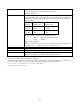
SPECIFICATIONS File Format Static, Panorama: JPEG standard; Movie: AVI/JPEG (for recording to CompactFlash card) Recording Medium CompactFlash card Standard Memory Capacity/ Static S (1280 x 960) / 14 (500KB/image) Number of Image Files/ F (1280 x 960) / 19 (352KB/image) Computer Output Image Size N (1280 x 960) / 33 (200KB/image) E (640 x 480) / 55 (112KB/image) Movie: File Format AVI 3.2seconds (320x240) / 8sets (896KB / image) 6.4seconds (320x240) / 4sets (1792KB / image) 9.
Power Supply Four AA-size alkaline or lithium batteries Four AA-size nickel-hydrogen rechargeable batteries (NP-H3) AC adaptor (AD-C620) Battery Life The values noted below indicate the number of hours before battery failure under normal operating temperature (25°C). These values are for reference only, and do not guarantee that any particular set of batteries actually will provide the service life indicated. Low temperatures shorten battery life.
BLOCK DIAGRAM 26pin Voltage regulator L-PCB ST-UNIT 10pin Photo sensor Comparator Battery voltage TFT controller BL-PCB 5.0V VCC2 10pin -14.5V VEE2 3.0V VDD 6.
ADJUSTMENT 1. Adjustments to be done (1) Whole unit 1. Loading ADJ program 2. White balance, Sensitivity 3. White scratch correction 4. Flash operation and charge current check 5. VCOM-DC adjustment 6. Current consumption Note: When the lens ass'y is replaced, adjustment should be done in order of above 1, 2, and 3. (2) D-PCB 1. Function check (3) L and BL PCBs 1. VCC2 adjustment and VCC13, VCC7, VEE2 voltage check 2. VCO free run frequency adjustment 3. Backlight drive voltage adjustment 4.
1. Whole unit 1-1. Loading ADJ program Camera mode: PLAY mode Necessary program: adj712f.exe,712_0212.adj and adj712k.exe Adjustments and Checks (1) Insert CompactFlash card and turn the camera on for PLAY mode. (2) Connect the camera‘s 3-pin jack and PC’s RS232C port with a link cable. PC QV-5500SX RS232C port Link cable (3) Execute adj712f.exe on Windows 95 or 98. (Fig. 1) (Fig. 1) (4) Open "712_0212.adj" file using File/Open command. (5) Click [Trans] button.
(6) The first ADJ program has been done when “send ok” is displayed. Close the program then execute “adj712k.exe”. (Fig. 4) (Fig. 4) (7) Click [Rgain*=1.07, Bgain*=1.09] button. ● If the program has been completed correctly, screen shows “Replace complete”. (Fig. 5) ● If the program has been erroneously executed, “11RcvERR00” will be shown. (Fig. 6) (Fig. 5) (Fig. 6) (8) The program ends.
1-2. White balance and sensitivity adjustments 1. Necessary equipment (1) Simplified viewer (e.g. Kenko Light Box handy5000) which is modified to be DC powered externally. (2) Power source (Output voltage; 0 ~ 10V over, output current; 0 ~ 1A over) (3) ND filter (ND20) (4) Color temperature conversion filter (LA50) *Though the above filters are provided from Casio as parts (refer to the parts list), they are also available from camera shops. 2.
1-3. White scratch correction 1. Necessary equipment (1) Simplified viewer (e.g. Kenko Light Box handy5000) which is modified to be DC powered externally. (2) Power source (Output voltage; 0 ~ 10V over, output current; 0 ~ 1A over) (3) Use two ND filter together, one ND10 and one ND20, placing one on the top of the other. *Though the ND filter is provided from Casio as parts (refer to the parts list), it is also available from camera shops. 2.
1-4. Flash operation and charge current check Conditions • Perform the checking after flash adjustment. • Provide 6.0 ±0.1V from DC in jack. • Turn the camera on REC mode. Adjustment and checking (1) Shoot a picture with flash on mode. (2) Shoot a picture with red-eye reduction mode. (3) Shoot a picture with macro mode. (4) Set the camera on play mode and check the pictures on the monitor screen. (5) Record trigger pulses of the above (1), (2), and (3) pictures on a digital oscilloscope.
Flash trigger waveform 1. Normal waveform CH1 TIME : 1 µ sec/DIV VOLTS : 1 V/DIV 1V 1µV 757µV UERT First positive pulse. OK if second positive pulse is shown. First negative pulse. ACQUIRE NORMAL 2 AVS 1 ENVELOPE REPET SAVE ON ON | OFF ON | OFF 2. NG waveforms when trigger skipping occurs. (1) When trigger skipping occurs on the first positive pulse. (2) When trigger skipping occurs on the first negative pulse.
1-5. VCOM DC adjustment Conditions 1. Test mode 50 % raster image 2. Provide 6.0 ± 0.05V voltage from DC in jack. Adjustment and checking (1) Execute 50 PERCENT GRAY on the test mode. • While pushing down Flash and shutter button, turn the camera on. • Push the Flash button twice then press MENU button (MENU 1 display will be shown.) • Select 50 PERCENT GRAY then press the shutter button. (2) Monitor the photo sensor amplifier output via a low-pass filter of cutoff frequency 60Hz.
2. D-PCBAssy 2-1. Operation check Condition Set the camera on play mode. Adjustment and checking 1. Clock pulse frequency Check if CP400 is 32.768 ± 0.002kHz 2. Procedures (1) Connect a PC and the camera with a link cable. (PC; COM port, Camera; 3-pin jack) (2) Store GP2JPEG test file (8 files) in a CompactFlash card. Ref.bay / Ref.cb / Ref.cr / Ref.jpg / Ref.y / Refdec.cb / Refdec.cr / Refdec.y (3) Insert the Compact flash in the camera. (4) Turn the camera on ( in Play mode). (5) Double click Dt712.exe.
3. L, BL PCBs Assy 3-1. VCC2 adjustment and VCC13, VCC7, VEE2 checks Adjustment and checking Adjust VR151 so that VCC2 (CP172) is 5.0 ± 0.02V. Turn the power off and make sure that all the voltages are 0V. Notes : VCC7 = 7.0 ~ 8.0V VCC13 = 11.8 ~ 13.7V VEE2 = -13.2 ~ -15.4V 3-2. VCC free run frequency adjustment Condition 1. Connect CP763 (SYF) and CP700 (GND). Adjustment Monitoring CP734 (HDB) with frequency counter, adjust VR755 so that the frequency is 15.734 ± 0.1kHz.
3-3. BL drive voltage adjustment Checking Make sure that CP900 (BL-VCC) is 5.4 ± 0.2V. 3-4. VCOM AC and VCOM DC coarse adjustment Adjustment (1) Check if VCOM output (CP716) amplitude is 6.6± 0.3V. (2) Adjust VR320 so that High level of VCOM output (CP716) becomes 4.8 ± 0.2V. High level 4.8 [V] 0 [V] –1.8 [V] VCOM (PC716) Power Supply Oscilloscope — 14 — amplitude 6.
3-5. Brightness voltage setting and contrast adjustment Condition Nature of signal : 10 step (NTSC) Adjustment (1) Execute GRAY SCALE (10STEP) on the test mode. • While pushing down Flash and shutter button, turn the camera on. • Push the Flash button twice then press MENU button (MENU 1 display will be shown.) • Select GRAY SCALE (10STEP) then press the shutter button. (2) Triggering with FRP (CP380) signal, adjust BOUT signal as described below.
4. PW PCB Assy 4-1. VCC18, VCC15, VEE7 adjustments Adjustment Apply 5.0 ± 0.05V on VCC1-1 and adjust VR120 so that VCC18 (CP121) is 22.0 ± 0.5V. Adjust VR125 so that VCC15 (CP125) is 15.5 ± 0.2V. Adjust VR130 so that VEE7 (CP133) is –8.0 ± 0.2V. Note Perform VCC15 adjustment after VCC18 adjustment is done.
DISASSEMBLY 1. Take CompactFlash card from the camera. 5. Open the battery cover and unhook the case. Hook 2. Remove the batteries. 6. Unhook the case using a screw driver. Hook 3. Remove 2 screws from side body of the camera. 7. Remove the upper case. Screws 4. Remove 1 screw from the bottom of the camera. 8. Remove the top case.
9. Open the battery cover and remove 1 screw. Screw 10. Unhook the battery holder. 13. Remove 3 screws on the key PCB. Screw 14. Disconnect the flat cable and remove key PCB. Flat cable Hook 11. Remove the frame block. 15. Peel off the insulation sheet from the bottom. Insulation sheet 12. Peel off the insulation sheet on the key PCB. 16. Remove a screw with washer affixing PW PCB.
17. Disconnect the cable from the camera unit. 21. Remove PW PCB. Cable 18. Lift the PW PCB. 22. Remove 1 screw affixing the flash block. Screw 19. Unsolder 3 wires (red, blue, white). 23. Remove the flash block. Blue White Red 20. Unsolder 3 wires (purple, green, yellow). 24. Prepare capacitor discharging jig. Peel high voltage caution seal.
25. Discharge the capacitor. Minus terminal 29. Unhook the battery holder. Plus terminal 26. Remove 2 screws affixing Flash PCB. Hook 30. Remove the battery holder. Screws 27. Remove the flash unit. 31. Remove a wire (black) from battery holder. 28. Remove 1 screw affixing battery holder. 32. Remove 3 screws affixing JK PCB.
nd 33. (2 screw) 37. Disconnect the cable from camera unit. Screw rd 34. (3 screw) 38. Remove D PCB. Screw st 35. Remove 2 screws from D PCB. (1 screw) st 39. Remove 2 screws affixing camera unit. (1 screw) Screw Screw nd 36. (2 screw) nd 40.
41. Remove camera unit. 45. Peel the cloth tape off. Cloth tape 42. Remove 1 screw from L PCB. st 46. Remove 2 screws from BL unit. (1 screw) Screw Screw nd 47. (2 screw) 43. Open L PCB. Screw 44. Disconnect the cable from LCD. 48. Remove BL unit.
49. Take the spacer out. Spacer 50. Remove LCD.
Cautions in assembly procedures 1. Solder battery holder wire after it is assembled. 2. Use cloth tape so that cases do not catch the LCD flat cable. 3. Position PLAY/REC switch knob so that it catches the switch.
EXPLODED VIEW 64 52 57 61 71 43 2 3 57 23 64 65 57 65 72 64 47 65 21 6 71 57 20 65 4 45 62 42 41 72 45 36 65 75 37 60 24 28 1 31 74 59 65 54 18 33 32 12 53 29 66 22 19 68 46 65 53 38 69 13 25 64 51 67 70 48 44 49 63 7 5 8 34 16 67 9 39 35 58 15 50 30 73 40 14 26 55 10 27 — 25 — 11 17 56
PARTS PRICE LIST MAIN BODY COMPONENT N Item Code No.
N N N N N N N N N N Item Code No.
DIGITAL PCB ASS'Y N N N N N N N N N N N Item Code No.
LINEAR PCB ASS'Y N Item D160 D161 D162 D163 D190 D300 D310 D757 D778 FU900 IC150 IC180 IC300 IC302 IC310 IC315 IC340 IC390 IC730 IC900 Q310 Q152 Q155 Q300 Q301 Q900 Q905 SW300 SW310 N T155 N N N N N N VR151 VR320 VR340 VR344 VR381 VR755 Code No.
POWER PCB ASS'Y N Item D100 D110 D120 D127 D130 D131 D140 D195 FU102 FU103 FU104 IC110 IC115 IC120 IC125 IC127 IC130 IC135 IC137 IC139 IC140 Q110 Q127 Q140 Q111 Q120 Q121 Q122 Q126 Q130 Q131 Q195 VR120 VR125 VR130 Code No.
JACK PCB ASS'Y N Item Code No. Parts Name CONNECTOR CN101 3502 2445 CONNECTOR FUSE FU100 2797 5594 FUSE/CHIP JACKS JK100 3501 6755 JACK/POWER JK101 3501 8197 JACK/MINI JK102 3502 2439 JACK Specification Applicable Q Price Code R 53309-1090 1 AC C PI-R429002 1 AC B HEC3600-010120 HSJ1169-019010 HSJ1456-01-220 1 1 1 AD AF AC C C C KEYBOARD PCB ASS'Y N Item C810 N D800 D801 D802 D803 D804 D805 D806 D807 D808 D810 Q800 SW800 SW802 SW803 SW804 SW805 SW806 SW807 SW808 N SW810 Code No.
PRINTED CIRCUIT BOARDS BL PCB (PCB-712BL) C PCB (PCB-712C) — 32 —
D PCB (PCB-712D) — 33 —
JK PCB (PCB-712JK) K PCB (PCB-712K) — 34 —
L PCB (PCB-712L) — 35 —
PW PCB (PCB-K777PW) — 36 —
SCHEMATIC DIAGRAMS DIGITAL CIRCUIT — 37 —
POWER CIRCUIT DIGITAL ANALOG — 38 —
LINEAR CIRCUIT — 39 —
C-PCB CIRCUIT — 40 —
K-PCB CIRCUIT — 41 —
BL-PCB CIRCUIT — 42 —
JK-PCB CIRCUIT JK-IN to PCB-PW GND Imput : DC 6V to Battery Box Battery – — 43 —
TROUBLESHOOTING 1 : Display failure on Video/LCD display is OK. • Setting of NTSC/PAL is incorrect. ➠ Charge the video setting that is right for the TV (Refer to user’s manual). • L board failure of JK board failure. ➠ Replace boards. 2 : Flash does not work. Unable to adjust (White 100 %). Unable to set to red eye reduction mode (Flashes only once). • Strobe unit failure. ➠ Replace strobe unit. 3 : No display when in REC mode. Display failure. • Connection failure of D board connector (CN540).
APPENDIX 1. The distinction method of a model. • A model is Judged on a rated plate. For U.S.A MODEL EXCEPT U.S.
Ver.1 : The following items were changed • SPECIFICATIONS (P.2) • PARTS LIST (P.26,27,28) The following items are added • APPENDIX 1. The distinction method of model (P.45) CASIO TECHNO CO.,LTD. Overseas Service Division Nishi-Shinjuku Kimuraya Bldg.