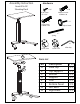
Assembly Instruction Hardware Item# 316-9X Standing Desk x 16 x 10 Small Screw F6 x 5/8” Medium Screw JCB M6 x 30 x6 x1 Large Screw JCB M6 x 40 Adjust Screw x1 Spring x1 x2 Caster Free x2 Allen Key Caster Lock A Parts List B C Part A B C D E F G H D E F G H Description Desk Top Top Support Roll bar Support Pole Bottom Panel Left Base Right Base Q’TY 1 PC 1 PC 1 PC 1 PC 1 PC 1 PC 1 PC 1 PC
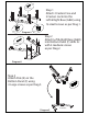
x 16 Small Screw Step 1 Attach 2 Casters Free and 2 Casters Lock into the Left & Right Base (G&H) using 16 small screws as per Diag.1. A H A G x2 x2 Diagram1. Caster Free x4 Caster Lock Step 2 Attach Left & Right Base (G&H) into Bottom Panel (F) drills its with 4 medium screws as per Diag.2. A H Medium Screw A G FA Diagram2. EA A H Step 3 Attach Pole (E) on the Bottom Panel (F) using 4 Large screws as per Diag.3. Diagram3.
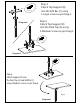
Step 4 Attach Top Support (B) into the Roll Bar (C) using 2 Large screws as per Diag.4. x2 Large Screw B Step 5 Attach Top Support (B) into the Desk Top (A) using 4 Medium screws as per Diag.5. Diagram4. C C x4 Medium Screw B A Diagram5. x2 C JCB M6 x 30 D Step 6 Attach Support (D) into the Desk Top (A) and Roll Bar (C) using 4 Medium screws as per Diag.6. B A Top Set Diagram6.
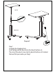
Top Set x1 Spring Bottom Set Diagram7. x1 Adjust Screw Step 7 Assembly the Standing Desk Insert Spring and the top set into the hole of bottom set, Then insert the adjust screw into the back of bottom set to locked the level that you need as per Diag.7.