HCC360 Domino Two Zone Ceramic Hob Manual for Installation, Use and Maintenance Passionate about style Customer Care Department • The Group Ltd. • Harby Road • Langar • Nottinghamshire • NG13 9HY T : 01949 862 012 F : 01949 862 003 E : service@cda.eu W : www.cda.
ENGLISH Instructions for use Dear Customer, Thank you for having purchased and given your preference to our product. The safety precautions and recommendations reported below are for your own safety and that of others. They will also provide a means by which to make full use of the features offered by your appliance. Please preserve this booklet carefully. It may be useful in future, either to yourself or to others in the event that doubts should arise relating to its operation.
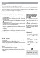
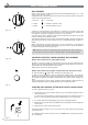
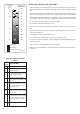
1 FEATURES “2 GAS” COOKING HOB (Fig. 1.1) 2 The appliance has class 3 COOKING POINTS 1. Semirapid burner (SR) - 1,75 kW 2. Rapid burner (R) - 3,00 kW CONTROL PANEL DESCRIPTION 1 Fig. 1.1 4 5 3 3. Burner 2 (R) control knob 4. Burner 1 (SR) control knob 5. Electric gas-lighting device; if the device is not installed, the appliance may be provided with: - A gas-lighter incorporated into the knob (★ symbol beside flame heat/max. gas flow). - No gas-lighter (no ★ symbol beside knobs). - max.
“2 ELECTRIC” COOKING HOB (Fig. 1.3) - Electrical isulation Class I. - Overheating surfaces protection Type Y. 2 COOKING POINTS 1. Electrical plate Ø 145 - (1000 W - 1500 W) 2. Electrical plate Ø 180 - (1500 W - 2000 W) 1 CONTROL PANEL DESCRIPTION 3. Electrical plate 1 control knob 4. Electrical plate 2 control knob 5. Power indicator light Fig. 1.3 3 5 4 VITROCERAMIC HOBS (Fig. 1.4, 1.5, 1.6, 1.7) - Electrical isulation Class I. - Overheating surfaces protection Type Y.
2 GAS COOKING HOBS GAS BURNERS Gas flow to the burners is adjusted by turning the knobs (illustrated in figs. 2.1a - 2.1b) which control the safety valves. Turning the knob so that the indicator line points to the symbols printed on the panel achieves the following functions: ✓ full circle Fig. 2.1a ● = closed valve ✓ symbol = maximum aperture or flow ✓ symbol = minimum aperture or flow To light one of the gas burners, hold a flame (e.g.
CHOICE OF BURNER DIAMETERS OF PANS WHICH MAY BE USED ON THE HOBS (fig. 2.4) The symbols printed on the panel beside the gas knobs indicate the correspondence between the knob and the burner. The most suitable burner is to be chosen according to the diameter and volume capacity of the container to be warmed. It is important that the diameter of the pots or pans suitably match the heating potential of the burners in order not to jeopardise the efficiency of the burners, bringing about a waste of gas fuel.
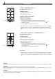
3 ELECTRIC COOKING HOBS NORMAL HOTPLATE 0 1 6 5 2 3 RAPID HOTPLATE (red dot) 4 The rapid hotplate control knob is similar to that of the normal hotplate, with 6 or 12 selectable heating positions (fig. 3.1 - 3.2). The characteristics of this hotplate, which is also equipped with a thermostatic cut-off device, make it possible to: – achieve the cooking temperature rapidly – make full use of its output power using flat-bottomed pans – limit the output power with unsuitable saucepans. Fig. 3.
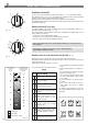
4 VITROCERAMIC HOBS The main characteristic of this pyroceram cooker top is that it permits rapid vertical transmission of the heat from the heating elements below to the saucepans on top. 0 1 The heat does not spread horizontally, however, and therefore the glass stays cold only a few centimetres from the hob. The hobs are controlled by the 7 positions switch (0÷6) (fig. 4.1) or by the continuous energy regulation switch (0÷12) (fig. 4.2).
Hob controlled by 7-position switch Hob controlled by continuous energy regulation switch 0-6 0 - 12 1 1 2 3 2 3 HINTS FOR SAFE USE OF THE HOBS – Before switching on, check which knob controls the required hob. You are advised to place the saucepan on the hob before switching on and to take it off after switching off. – Use saucepans with an even flat bottom (be careful of cast iron saucepans). Uneven bottoms can scratch the pyroceram surface. Check that the bottom is clean and dry.
5 CLEANING AND MAINTENANCE GENERAL RECOMANDATION VITROCERAMIC HOB ✓ Before you begin cleaning you must ensure that the hob is switched off. It is advisable to clean when the appliance is cold and especially when cleaning the enamelled parts. ✓ All enamelled surfaces have to be washed with soapy water or some other non-abrasive product with a sponge and are to be dried preferably with a soft cloth. ✓ Avoid leaving alkaline or acid substances (lemon juice, vinegar etc.) on the surfaces.
BURNERS AND GRIDS ✓ These parts can be removed and cleaned with appropriate products. ✓ After cleaning, the burners and their flame distributors must be well dried and correctly replaced. ✓ It is very important to check that the burner flame distributor and the cap has been correctly positioned - failure to do so can cause serious problems. ✓ In appliances with electric ignition keep the electrode clean so that the sparks always strike.
Installation advice 6 INSTALLATION IMPORTANT – The appliance should be installed, regulated and adapted to function with other types of gas by a QUALIFIED INSTALLATION TECHNICIAN. Failure to comply with this condition will render the guarantee invalid. – The appliance must be installed in compliance with regulations in force. – Installation technicians must comply to current laws in force concerning ventilation and the evacuation of exhaust gases.
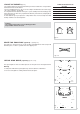
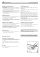
;;;;;;; @; ; @; @ ; @; @ Fig. 6.3 30 mm ;;;;; ; ;; ;;;;;;; Clearance Cupboard door Space for connections A A A A WITH CUPBOARD DOORS (fig. 6.3) The fixture has to be made according to specific requirements in order to prevent the gas burners from going out, even when the flame is turned down to minimum, due to pressure changes while opening or closing the cupboard doors. It is recommended that a 30 mm clearance be left between the cooker top and the fixture surface beneath it.
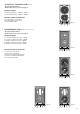
ELECTRICAL PLATES AND VITROCERAMIC COOKING HOBS 288 510 288 30 510 50 50 490 490 + – 20 0 27 +02 – Fig. 6.8a + – 20 70 +02 – 2 Fig. 6.8b TECHNICAL INFORMATION FOR THE INSTALLER Before installing the cooktop, remove the protective film. 650 mm In order to install the cooker top into the kitchen fixture, a hole with the dimensions shown in figs. 6.8a and 6.
FASTENING THE COOKTOP A A Each cooker top is provided with an installation kit including brackets and screws for fastening the top to fixture panels from 20-30 to 40 mm thick, figs. 6.11 (2 electrical plates hob) e 6.12 (vitroceramic hob). ✓ Cut the unit. A A ✓ Stretch gasket “D” over the edge of the hole made, being careful to overlay the junction edges ✓ Turn the cooktop over and put tabs “A” (fig. 6.10) into the mountings, only tighten screws “B” a few turns.
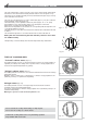
7 GAS SECTION GAS CONNECTIONS C Make sure that the hob is adapted to function with the type of gas supply available (see label). If not, refer to the section headed “Adapting the appliance to function with different types of gas”. F GASES 1/2” G The gases used for the operation of cooking appliances may be grouped by their characteristics into two types: – Liquid gas: Butane gas (G 30) and Propane gas (G 31) – Natural gas (G 20) F G 1/2" G conical Connecting to gas mains: GB Cat: A Fig. 7.
INJECTORS TABLE GB Cat: II 2H3+ NOMINAL POWER REDUCED POWER G30/G31 28-30/37 mbar G20 20 mbar BURNERS [Hs - kW] [Hs - kW] Ø injector [1/100 mm] Ø injector [1/100 mm] 1,75 0,45 65 97 Semi-rapid (SR) Rapid (R) 3,00 0,75 85 115 Triple ring (TR) 3,50 1,50 95 135 OPERATIONS TO BE PERFORMED WHEN SUBSTITUTING THE INJECTORS J ✓ Remove the gratings, the burner covers and the knobs; ✓ Using a wrench substitute the nozzle injectors “J” (Fig. 7.3 - 7.
8 ELECTRICAL SECTION IMPORTANT: Installation has to be carried out according to the instructions provided by the manufacturer. Incorrect installation might cause harm and damage to people, animals or objects, for which the manufacturer accepts no responsibility.
REPAIRS REPLACING THE POWER SUPPLY CABLE (for 2 electrical plates and vitroceramic models) Turn the cooktop over and unhook the terminal board cover by inserting a screwdriver into the two hooks “A” (fig. 8.1). Open the cable gland by unscrewing screw “F” (fig. 8.2), unscrew the terminal screws and remove the cable. The new supply cable, of suitable type and section, is connected to the terminal board following the diagram fig. 8.3.
8 PARTE ELÉCTRICA Importante: A instalação deve ser efetuada conforme as instruções do fabricante. Uma instalação erronea pode causar danos às pessoas, animais ou coisas e defronte a tais acontecimentos o fabricante não pode ser considerado responsável. LIGAÇÃO À REDE ELÉCTRICA ✓ A ligação à rede eléctrica deve ser feita por técnicos qualificados e em conformidade com as normas vigentes.
Cod.