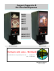
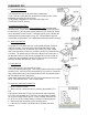
Compact Cappuccino & Hot Chocolate Dispensers Models: •GB1CP •GB2CP •GB3CP •GB1HC-CP •GB2HC-CP •GB1HC-CP-PC* •GB2HC-CP-PC* GB1HC-CP (shown) GB2-CP (shown) Cecilware sells value...
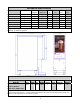
Mechanical Specifications Model # Label No. of Hopper Width Dept Hight Hoppers Capacity (lb.) (in.) (in.) (in.) GB1CP Cappuccino 1 8 lb. 7.75 18.625 26 GB2CP Cappuccino 2 4 lb. 7.75 18.625 26 GB3CP Cappuccino 3 4 lb. 10.5 18.625 26 GB1HC-CP 8 lb. 7.75 18.625 26 Hot Chocolate 1 GB2HC-CP Hot Chocolate 2 4 lb. 7.75 18.625 26 GB1HC-CP-PC Hot Chocolate 1 8 lb. 7.75 18.625 26 GB2HC-CP-PC Hot Chocolate 2 4 lb. 7.75 18.625 26 Add an additional 4” when installing with 4” legs.
I. INSTALLATION INSTRUCTIONS This equipment is to be installed to comply with the applicable Federal, State, or local plumbing codes having jurisdiction. In addition: 1. A quick disconnect water connection or enough extra coiled tubing (at least 2x the depth of the unit) so that the machine can be moved for cleaning underneath. 2. An approved back flow prevention device, such as a double check valve to be installed between the machine and the water supply.
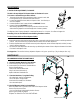
ADJUSTMENTS A. WATER FLOW ADJUSTMENTS, FLOW RATE The Unit Is Factory Adjusted To Dispense Water At The Rate of 4 oz/sec. To increase or decrease flow, proceed as follows: 1. Remove Left side panel and locate Dispense Valve mounted on tank, with Flow Adjuster facing up, underneath cold water reservoir. 2. Locate Flow Adjustment Screw (white) on Dispense Valve. Use Allan Key to reach Flow Adjuster. 3. Rotate Adjustment Screw Counterclockwise to INCREASE flow rate. 4. Rotate Clockwise to DECREASE flow rate.
COMPONENTS TEST A) Thermostat Adjustments: The Thermostat is factory set for proper dispense temperature of 190° F with the control shaft set to the maximum clockwise position. If field adjustments are needed proceed as follows: To DECREASE temperature, turn the control shaft slightly in the COUNTERCLOCKWISE direction. For qualified technicians ONLY: Remove the knob and locate the Slotted Adjustment Screw inside the hollow thermostat shaft.
TROUBLESHOOTING GUIDE WARNING: To reduce the risk of electrical shock unplug the dispenser power cord before repairing or replacing any internal components of the unit.. Before any attempt to replace a component be sure to check all electrical connections for proper contact. PROBLEM PROBABLE CAUSE REMEDY 1 A Dispensing unit unplugged Reconnect dispensing unit Light Display B No power from Terminal Block Check the Terminal Block for loose wire not lit. C Defective Bulb Replace Bulb. No power.
CLEANING AND SANITIZING Sanitizing: All sanitizing agents in the food zone must comply with 21 CFR 178.1010. All food dispensing units should be sanitized periodically. All parts to be sanitized must be cleaned first. To prepare a sanitizing solution: Add 2 Tsp. Of Liquid Clorox Bleach (5.25% Concentration) To 1 gallon Of Water At Room Temperature (70°- 90°F). Note: Always start with a unopened bottle of Clorox Bleach since the solution from an opened bottle has a short life span.
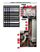
INTERNAL COMPONENTS IDENTIFICATION Tank Top View TANK ASSEMBLY SK89Q ITEM P/N QTY DESCRIPTION 1 SK88A 1 Tank Top 2 L681A 1 Thermostat & Probe M008A 1 Thermostat Knob 3 G267A 1 Heater 120v 1700w MO18A 1 Gasket, Tank Heater 4 P446A 4 1/4-20x5/8 SS SL Hex Washer Hd Scr 5 M461A 6 Silicone Seal (.
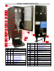
EXTERNAL COMPONENTS IDENTIFICATION 1 2 3 4 5 6 7 8 9 10 19 11 20 22 12 18 13 17 14 21 15 ITEM 10 16 11 ITEM 1 2 3 4 5 6 7 8 9 P/N SS42A SS51A CD161 CD155 M705A CD70A CD234 CD246 CD374 CD373 CD61A CD254 CD67A CD137 CD124 QTY 1 2 1 2/3 1 1 1 1 1 1 1 1 1 1 1 DESCRIPTION Top Cover Side Panels Hopper 8lb GB1 Hopper 4lb GB2, GB3 Door Latch Product Guide GB1, GB3 Product Guide Right GB2 Product Guide Left GB2 Product Guide Right GB3 Product Guide Left GB3 Steam Deflector GB1, GB2 Steam Deflector GB3