
User's Manual

2 I ENGLISH
Your NexStar tracks celestial objects with its altitude-azimuth
motor drive. Objects will stay centered in the telescope’s fi eld
of view, but with alt-az tracking they will rotate over time. This
limits the potential exposure time when using the telescope for
astrophotography. The Wedge tilts the telescope’s azimuth
axis so that it tracks stars as they move in an arc around the
celestial pole. This keeps objects centered without rotation,
allowing you to take longer exposure astrophotos.
Your wedge comes mostly assembled out of the box. However,
you will need to attach the latitude adjustment rod and may
need to adjust the side latitude plate depending on your location.
Part List
• Wedge Assembly
• Fork arm attachment
bolt with washer
• 10mm hex key
• 8mm hex key
• 6mm hex key
• 5mm hex key
• 2.5mm hex key
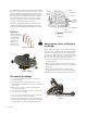
Assembling the Wedge
1. Loosen the two latitude locking knobs on both sides of
the wedge (Figure 2).
2. Push the tilt plate all the way forward as far as it will go,
and hand tighten the latitude locking screws to hold the tilt
plate in place.
3. Remove the two screws from each of the L-brackets on
the bottom of the tilt plate.
4. Place one end of the swivel block into one of the top holes
on the inside of the L-bracket.
5. Once one side of the swivel block is in place, reattach the
screws to hold the L-bracket to the tilt plate.
6. Attach the remaining L-bracket to the bottom of the tilt plate
making sure the other end of the swivel block fi ts inside the
corresponding hole on the bracket. Tighten both brackets.
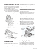
Adjusting the Center of Gravity of
the Wedge
Before mounting a telescope to your wedge you may wish to
change its center of gravity by shifting the wedge side plates
forward. The side plates can be moved forward if you are
observing from a higher latitude (50° or higher). This will place
the telescope’s center of gravity closer to the center of your
tripod for maximum stability. To adjust the side plates:
1. Loosen the two latitude locking knobs on both sides of
the wedge (Figure 2).
2. Push the tilt plate all the way forward as far as it will go,
and hand tighten the latitude locking knobs to hold the tilt
plate in place.
3. Slide the entire wedge forward so that the holes line
up with the front three holes on the base plate. (Figure 3).
4. Replace the screws in the side plates in their new position.
Figure 1.1 Hardware
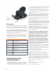
Figure 1.2 Wedge
Figure 2
Figure 3
Tilt Plate
Swivel Block
Latitude
Adjustment Knob
L-Bracket
Latitude Bar
Latitude
Locking
Knobs
Latitude
Locking
Knobs