Floor jack transmission adapter 39152 Set up and Operating Instructions Visit our website at: http://www.harborfreight.com Read this material before using this product. Failure to do so can result in serious injury. Save this manual. Copyright© 2002, 2009 by Harbor Freight Tools®. All rights reserved. No portion of this manual or any artwork contained herein may be reproduced in any shape or form without the express written consent of Harbor Freight Tools.
Save This Manual NOTICE is used to address practices not related to personal injury. Keep this manual for the safety warnings and precautions, assembly, operating, inspection, maintenance and cleaning procedures. Write the product’s serial number in the back of the manual near the assembly diagram (or month and year of purchase if product has no number). Keep this manual and the receipt in a safe and dry place for future reference.
when operating the tool. Do not use the tool while tired or under the influence of drugs, alcohol, or medication. A moment of inattention while operating the tool increases the risk of injury to persons. b. Dress properly. Do not wear loose clothing or jewelry. Contain long hair. Keep hair, clothing, and gloves away from moving parts. Loose clothes, jewelry, or long hair increases the risk of injury to persons as a result of being caught in moving parts. c. Do not overreach.
Symbols and Specific Safety Instructions for this product is dangerous and can lead to serious injury or property damage. 2. If in doubt about the safety of your project, have the work done by a professional familiar with applicable safe practices. 3. Use only with 2-1/4 Ton Floor Jack (such as SKU 50183 Heavyweight Floor Jack, sold separately). 4. Always evaluate your task before using this Adapter. This adapter is designed to support a transmission or a differential as individual components.
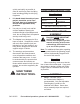
8. 9. quickly and safely as possible in order to avoid injury from the falling load, including getting hit with flying fragments. Functional Description If in doubt about the safety of your project, we advise you to have the work done by a professional familiar with applicable safety practices. Weight Capacity 880 lb. Base Tilt 60° Forward 10° Backwards Saddle Pin Diameter .
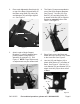
2. Place each Adjustable Steel Angle (6) on top of the Base (38) and fasten to the Base using Bolts (30), Nuts (28) and Washers (29) and finger tighten on. See Figure 1. 4. 6 The Chain (5) comes assembled to one of the Angle Support Brackets. See Figure 2. Use Nut (23), Eye Bolt Pin, (25) and Wing Nuts (26) to attach Hook Bolt (22) to Support Bracket on opposite corner from Chain. See Figure 3. 26 38 1 25 23, 26 22 28, 29, 30 6 Figure 1 3.
. The bottom of the Base Shaft (18) is then securely placed into the saddle of the Transmission Jack to firmly hold the Transmission Adapter in place. See Figure 5. Operating Instructions Read the entire Important Safety Information section at the beginning of this manual including all text under subheadings therein before set up or use of this product. Inspect tool before use, looking for damaged, loose, and missing parts. If any problems are found, do not use tool until repaired.
Bolt (22). Turn the nut to retract the bolt and hold the transmission snugly. 7. Follow the steps in your vehicle’s Owner’s Service Manual, remove drive shaft and any and all mounting bolts and/or nuts. 8. Depending on type of transmission, you may need to move Jack and transmission back a few inches to free input shaft of the transmission. 9. Prior to moving the transmission, double-check that it is secured to the Transmission Adapter. 10.
INSPECTION, MAINTENANCE, AND CLEANING 2. Before each use, inspect the general condition of the Transmission Jack. Check for oil leaks, jack operation, loose components, free rotation and pivoting of saddle adjustment components. If a problem occurs, have the problem corrected before further use. Do not use damaged equipment. 3. Periodically, lubricate all pivot points. 4. To clean, use a mild detergent and then dry. 5.
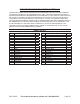
PLEASE READ THE FOLLOWING CAREFULLY The manufacturer and/or distributor has provided the parts list and assembly diagram in this manual as a reference tool only. Neither the manufacturer or distributor makes any representation or warranty of any kind to the buyer that he or she is qualified to make any repairs to the product, or that he or she is qualified to replace any parts of the product.
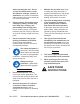
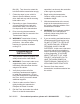
ASSEMBLY DIAGRAm 1 2, 3, 4 5 6 7, 8, 9 12 28, 29, 30 11 10 13 27 14 26 31, 32, 33, 34 35, 36, 37 23, 22, 25 22 17 16 15 38 18 21 SKU 39152 20 19 For technical questions, please call 1-800-444-3353.
LIMITED 90 DAY WARRANTY Harbor Freight Tools Co. makes every effort to assure that its products meet high quality and durability standards, and warrants to the original purchaser that this product is free from defects in materials and workmanship for the period of 90 days from the date of purchase.