
Installation guide

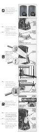
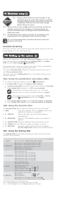


8A.1. Insert the camlock key and
rotate it 90° clockwise.
This will
allow for the removal of the
cover, as well as for the
rotation of the Manual
Release thumbwheel.
8A.2. The motor pinion can be
put into ‘Manual Mode’
(unlocked) by rotating the
Manual Release
thumbwheel counter-
clockwise through
approximately 90°.
Using the camlock, it is possible to lock the operator cover in place
with the Manual Release thumbwheel in either the ‘locked’ or
‘unlocked’ position
When locked, the Manual Release thumbwheel cannot be moved
from ‘locked’ to ‘unlocked’ or vice versa
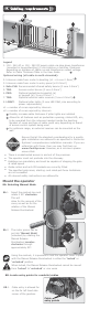
Mount the operator
8A. Selecting Manual Mode
Ensure that all the standard considerations for a quality
gate installation are adhered to as specified in Centurion
Systems’ comprehensive installation manuals. If you are
unfamiliar with these, then you may find them on
www.CentSys.com. However, as a minimum please
ensure that:
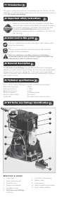
Legend
1. 10V - 24V AC or 10V - 28V DC supply cable via step-down transformer
(mounted in house/dwelling) (2 core cabtyre or twinflex, thickness
depending on distance of cable run and transformer output voltage.
Refer to Cable Thickness Table in the User Guide
Optional wiring (all cable is multi-stranded):
2
2. Intercom cable from motor to dwelling (n1 + 6 core 0 .5mm )
2
3. Intercom cable from motor to entry panel (n2 0.5mm )
2
4. Safe CLS: Recommended infrared safety beams (3 core 0.5mm )
2
5. TRG: Access control device (3 core 0.5mm )
6. PED: Optional pedestrian keyswitch (a)
2
or keypad (b) (3 core 0.5mm )
2
7. TRG: Optional external radio receiver (3 core 0.5mm )
8. LIGHT: Optional pillar lights (3 core LNE SWA, size according to
power requirements)
n1 = number of cores required by intercom
n2 = number of cores required by intercom
Possibly increase cable thickness if pillar lights are installed
Allows for all features such as pedestrian opening, status LED, etc.,
to be operated from the intercom handset inside the dwelling.
Number of cores and type of cable could vary depending on brand
of access control system being used
For optimum range, an external receiver can be mounted on the
wall
8B. Locate entry points for conduits/cables
8B.1. Cable entry is allowed for
on the far left hand side
corner of the gearbox.
Cable
entry points
4
6
5
7
8
8
3
1
2
There is unobstructed access in and out of the premises
The operator must not protrude into the driveway
Endstops are mandatory and must be capable of stopping the gate
at rated speed
Guide-rollers and anti-lift brackets are correctly fitted
The specified gate mass, starting- and rated-pull-force limitations
are not exceeded
All relevant safety instructions are adhered to