
Installation guide


A-1 Automatic; Start with gate closed
B-1 Learn a transmitter button to TRG
B-2 Learn a transmitter button to PED
B-3 Learn a transmitter button to LCK
B-4 Delete a transmitter
B-5 Delete all transmitters
C-1 Autoclose off
C-2 Autoclose after 5 seconds
C-3 Autoclose after 10 seconds
C-4 Autoclose after 15 seconds
C-5 Autoclose after 30 seconds
C-6 Autoclose after 45 seconds
D-1 Standard Mode
D-2 Open Only Mode
D-3 Reversing Mode
D-4 PIRAC Mode On Off
D-5 Pre-Flash Mode A On Off
D-6 Pre-Flash Mode B On Off
E-1 Positive Close Mode
E-2 Speed Hi Lo
E-3 Sensitivity Hi Lo
E-4 Backup to Backup Memory Module
E-5 Restore from Backup Memory Module
Function dial
A - LIMITS
B - REMOTES
C - AUTOCLOSE
D - MODE
E - PROFILE
Setting dial (Ring position-Dial position)
Use toggle pushbutton to select preference.
For D - MODE, green status LED=On; red status LED=Off
For E - PROFILE, green status LED=High; red status LED=Low
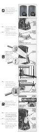
Connect all wiring
Wire the controller to the required input and output devices as per the
wiring diagrams on the right-hand side.
All programming is done by means of two rotary dials, a pushbutton,
and the bi-colour (red and green) status LED.
The rotary Function Dial selects the required function you wish to
set. This is selected first.
Secondly, the rotary Setting Dial dials in the actual setting for the
function selected.
10A. Using the pushbutton and status LEDs
To select a particular setting, press the pushbutton
The status LED indicates the status of the setting
A green status LED indicates that particular setting is selected
A red status LED indicates it is Off or not selected
If the setting is a single fixed value, e.g. 15 second
Autoclose time, then the pushbutton acts as a select.
If the setting has an option such as On/Off, or Hi/Lo
then the pushbutton will act as a toggle.
If the status LED is green, then the first option is selected
If the status LED is red, then the second option is selected
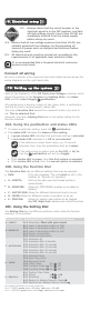
Refer to the illustration of the D2 Turbo Low-Voltage controller, which
shows the position of the Function and Setting Dials, the status
LED, and the select/toggle pushbutton.
10B. Using the Function Dial
The Function Dial has six different settings that may be selected:
RUN: Fully anti-clockwise. The unit must be left in this
position for ‘Normal run’ operation
A - LIMITS: Sets up the gate open and closed positions
automatically
B - REMOTES: Allows for CENTURION remotes to be added or
deleted
C - AUTOCLOSE: Allows for different Autoclose times to be set
D - MODE: Allows for different modes of operation to be set
E - PROFILE: Allows for specific gate profiles to be toggled
On/Off, High/Low, backup and restore functions
10C. Using the Setting Dial
The Setting Dial has six different positions, which allow the function
required, to be selected.
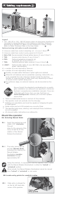
9.1. Always check that the circuit breaker in the
electrical panel is in the OFF position, and that
all high-voltage circuits (more than 42.4V) are
completely isolated from the mains supply
before doing any work.
9.2. Ensure that all low-voltage systems (less than 42.4V) are
suitably protected from damage, by disconnecting all
sources of power such as chargers and batteries before
doing any work.
9.3. All electrical work must be carried out according to the
requirements of all applicable local electrical codes.
It is recommended that a licensed electrical contractor
perform such work.