INSTALLER / CONSUMER SAFETY INFORMATION PLEASE READ THIS MANUAL BEFORE INSTALLING AND USING APPLIANCE. WARNING! IF THE INFORMATION IN THIS MANUAL IS NOT FOLLOWED EXACTLY, A FIRE OR EXPLOSION MAY RESULT CAUSING PROPERTY DAMAGE, PERSONAL INJURY OR LOSS OF LIFE. FOR YOUR SAFETY Jefferson Direct Vent/Natural Vent Gas Heater Model: JDVBRN Installation and service must be performed by a qualified installer, service agency or the gas suppler. WHAT TO DO IF YOU SMELL GAS: • Do not try to light any appliance.
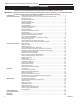
Jefferson Direct Vent/Natural Vent Gas Heater Table of Contents PLEASE READ THE INSTALLATION & OPERATING INSTRUCTIONS BEFORE USING APPLIANCE. Thank you and congratulations on your purchase of a CFM Corporation stove. IMPORTANT: Read all instructions and warnings carefully before starting installation. Failure to follow these instructions may result in a possible fire hazard and will void the warranty.
Jefferson Direct Vent /Natural Vent Gas Heater Installation & Operating Instructions The Jefferson Direct Vent/Natural Vent Room Heater, Model No. JDVBRN, is a vented gas appliance listed to the ANSI standard Z21.88-2005 and CSA-2.33-2005 for Vented Room Heaters, and CSA 2.17-M91, Gas-Fired Appliances For Use at High Altitudes. The installation of the Jefferson Direct Vent/Natural Vent Room Heater must conform with local codes, or in the absence of local codes, with National Fuel Gas Code, ANSI Z223.
Jefferson Direct Vent/Natural Vent Gas Heater Installation & Operating Instructions Requirements for the Commonwealth of Massachusetts All gas fitting and installation of this heater shall only be done by a licensed gas fitter or licensed plumber.
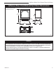
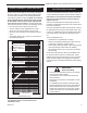
Jefferson Direct Vent /Natural Vent Gas Heater Jefferson Direct Vent/Natural Vent Stove Dimensions See Page 6 for Flue Collar Centerline Dimensions. 28���" (724 mm) Valve Inlet C L 3" (76 mm) 24" (610 mm) 14���" (368 mm) 8" (203 mm) 4188 Fig. 1 Jefferson dimensions. ST205 FDV28 dimensions 12/3/99 djt Attention The Jefferson stove is shipped from the factory as a Direct Vent Gas Heater. This heater may be converted into a Natural Vent unit in the field.
Jefferson Direct Vent/Natural Vent Gas Heater Installation Requirements The installation must conform with local codes or, in the absence of local codes, with the National Fuel Gas Code, ANSI Z223.1/NFPA 54 - latest edition. (EXCEPTION: Do not derate this appliance for altitude. Maintain the manifold pressure at 3.5” w.c. for Natural Gas, and 10” w.c. for Propane). In Canada, installation must be in accordance with the current CSA B-149.1 Installation Codes and/or local codes.
Jefferson Direct Vent /Natural Vent Gas Heater Parallel Installation: Minimum Clearance and Flue Centerline, Direct Vent and Natural Vent Wall Centerline from Floor C L C A D A C L B ST131a Stove Clearances A: 4” (102 mm) B: 4” (102 mm) C: 14¹⁄₂” (369 mm) D: 9” (229 mm) Pipe Centerlines ST128a ST128a FDV28 Fig. 3 Parallel installation, minimum back and side clearances and flue centerlines.
Jefferson Direct Vent/Natural Vent Gas Heater Horizontal Termination Direct Vent ONLY Gas Specifications Model Fuel Gas Control Max. Input BTU/h JDVBRN JDVBRP Nat Prop Millivolt Millivolt 28,000 28,000 Min. Input BTU/h 20,000 19,000 Weight: Fully assembled; 350 lbs. Gas Inlet and Manifold Pressures Inlet Minimum Natural 5.5” w.c. Inlet Maximum 14.0” w.c. 14.0” w.c. Manifold Pressure 3.5” w.c. 10” w.c.
Jefferson Direct Vent /Natural Vent Gas Heater Vertical Termination - Direct Vent ONLY Vent Termination Clearances A vertical vent system must terminate no less than 8’ (2.44 m) and no more than 40’ (12 m) above the appliance flue collar. A 2¹⁄₄" restrictor plate (supplied) must be used, where specified, in all vertically terminated vent systems. (Refer to Figure 8) NOTE: The restrictor plate supplied with the vertical termination should be discarded.
Jefferson Direct Vent/Natural Vent Gas Heater Vent Termination Clearances Your stove is approved to be vented either through the side wall, or vertical through the roof. • CFM Corporation does not require any opening for inspection of vent pipe. • Only CFM Corporation and Simpson DuraVent venting components specifically approved and labelled for this stove may be used. • Minimum clearances between vent pipes and combustible materials is one (1”) inch (25 mm), except where stated otherwise.
Jefferson Direct Vent /Natural Vent Gas Heater General Venting Information - Termination Location INSIDE CORNER DETAIL G V H A N N D L V E C B V F B ����� ������ B V Ope Operable rable V B B B V J X X AIR SUPPLY INLET M I A CFM145a V VENT TERMINATION V Fixed Closed C = Clearance to permanently closed window D = Vertical clearance to ventilated soffit located above the terminal within a horizontal distance of 2’ (610mm) from the center line of the terminal E = Clearance to unve
Jefferson Direct Vent/Natural Vent Gas Heater Termination Clearances Termination clearances for buildings with combustible and noncombustible exteriors. Inside Corner Alcove Applications* Outside Corner G= Combustible 6" (152 mm) G F= Combustible 6" (152 mm) Noncombustible 2" (51 mm) V Noncombustible 2" (51 mm) V C V E O F Balcony with perpendicular side wall Balcony with no side wall D C E = Min. 6” (152 mm) for non-vinyl sidewalls Min. 12” (305 mm) for vinyl sidewalls O = 8’ (2.4 m) Min.
Jefferson Direct Vent /Natural Vent Gas Heater Venting Requirements and Options Direct Vent ONLY Approved Vent System Components The Jefferson Heater must be vented to the outdoors through an adjacent exterior wall or through the roof. The venting system must be comprised of the appropriate listed venting components specified on this page. These parts are available from DuraVent Corporation or your CFM Corporation Dealer. Refer to Figure 4 for dimensions relevant to the standard minimum-vent kits.
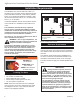
Jefferson Direct Vent/Natural Vent Gas Heater Assembly Procedures WARNING Failure to position the parts in accordance with these diagrams or failure to use only parts specifically approved for use with this heater may result in property damage or personal injury. This heater and components are heavy. Have help available for assembly. Tools Required • Phillips screwdriver (stub) • power drill • utility knife • reciprocating saw • metal drill bit: size 28 (.140”/3.
Jefferson Direct Vent /Natural Vent Gas Heater 3. Attach the fan to the rear shroud by engaging the upper flange of the fan skirt under the lower edge of the shroud and secure the skirt with the four screws and one star washer provided. (Fig. 14) 4. The rheostat control switch attaches to the left side of the valve bracket at the front of the stove. • Remove the plug from the rheostat bracket.
Jefferson Direct Vent/Natural Vent Gas Heater First Section of Vent Pipe 1/4”-20 x 1/2” Phillips Screw ENT CEM 4” Inner Starter Pipe ST211 Fig. 17 Connect the inner starter with the next section of inner vent pipe. 4. Attach the Inner Vent Assembly to the stove. ST211 • Run a bead of sealant around the bottom end of attach inner pipe the starter pipe and attach the assembly to the stove to next section using three 1/4-20 x 3/8” Phillips screws provided in 12/4/99 the parts bag. (Fig.
Jefferson Direct Vent /Natural Vent Gas Heater 12” (305mm) Max. Length Sleeve #8 Sheet Metal Screws ST356 Fig. 21 Simpson Dura-Vent - install outer adapter pipe. Firestop Side Wall Termination Assembly 1. Locate the vent opening on the wall. Refer to Page 7, Figure 5, to determine the opening centerline. It may be necessary to first position the stove and measure to find the hole location.
Jefferson Direct Vent/Natural Vent Gas Heater 6. Install the elbow using 3 sheet metal screws at each joint. 7. Measure, and cut if needed, the appropriate length of pipe section needed to make the connection through the wall. Include a 2” overlap; i.e. from the elbow to the outside wall face, about 2” or the distance required if installing a second 90° elbow. (Fig. 25) 8. Slip the wall plate and trim collar over the interior end of the horizontal pipe and install into the wall sleeve.
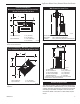
Jefferson Direct Vent /Natural Vent Gas Heater Wall Screws and Anchors Waterproof Seal Around PIpe Firestop Snorkel Termination Cap 4” Clearance Gravel Drain Window Well 3. Cut the opening: CFM System: 9³⁄₈” x 9³⁄₈” (240 x 240 mm) DuraVent System: 10” x 10” (254 x 254 mm) 4. Plumb any additional opening through the roof or other construction that may be needed. In all cases, the opening must provide a minimum of 1” (25 mm) clearance to the vent pipe. 5. Place the stove in its final position. 6.
Jefferson Direct Vent/Natural Vent Gas Heater Decorative 7” Pipe Use three #5 sheet metal screws at each joint Sealant CFM outer pipe (7FSSK) may be used after Draft Hood up to the ceiling. 4” B-vent Pipe Storm Collar Draft Hood Adapter Upper edge of flange goes under upper shingles #7DVSKV (A, B, or F) Roof Support Flashing ST221 Fig. 31 Roof support and flashing. up to the ceiling, then B-vent pipe must be used. Do not mix types of B-vent pipe; use components from one maker or the another.
Jefferson Direct Vent /Natural Vent Gas Heater Install the Log Set 1. Remove the logs from their packaging and inspect each piece for damage. DO NOT INSTALL DAMAGED LOGS. Figure 34 2. Install the rear log (1) by centering it side to side on the sheet metal shelf at the back of the firebox. (Fig. 34) 3. Install the left (2), and right (3) middle logs by engaging holes on their bottoms with pins on the burner brackets. (Fig.
Jefferson Direct Vent/Natural Vent Gas Heater Connect the Gas Supply Line Burner Information Check the Rating Plate attached by a steel cable to the firebox, to confirm that you have the appropriate firebox for the type of fuel to be used. The Jefferson may be converted from one gas to another using the appropriate Fuel Conversion Kit listed on Page 34. The appliance must only use the gas specified on the rating plate, unless converted using a CFM Corporation Fuel Conversion Kit.
Jefferson Direct Vent /Natural Vent Gas Heater Reassemble the shutter to allow the rear injector air inlet to close from a minimum 1/2” opening to fully open. (Fig. 40) You may have to try more than once to find the correct air shutter opening for best results depending on your altitude. See Table 1 Air Shutter (Original Position) Burner ST352 ST229a Fig. 37 Remove stove front. 3.
Jefferson Direct Vent/Natural Vent Gas Heater Install the Stove Front Left Burner Leg Injector Orifices 90° ST353a Fig. 41 Remove and replace injector orifices. The front panel attaches to the stove by four (4) steel tabs that engage with corresponding cast ribs on the sides and bottom of the stove body. Position the front about 3” down from the stove top and lift the plate to engage the upper tabs behind the adjacent ribs on the side. (Fig.
Jefferson Direct Vent /Natural Vent Gas Heater Operation Flame Characteristics Your First Fire Read these instructions carefully and familiarize yourself with the burner controls shown in Figure 47. Locate the pilot assembly, Figure 46. Follow the lighting instructions on Page 26 exactly. It is important to periodically perform a visual check of the pilot and the burner flames. Compare them to Figures 48, 49, 50. If any of the flames appear abnormal, call a service person.
Jefferson Direct Vent/Natural Vent Gas Heater Lighting and Operating Instructions FOR YOUR SAFETY READ BEFORE LIGHTING WARNING:If you do not follow these instructions exactly, a fire or explosion may result causing property damage, personal injury or loss of life. A. This heater has a pilot which must be lit manually. When lighting the pilot follow these instructions exactly. B. BEFORE LIGHTING smell all around the heater area for gas.
Jefferson Direct Vent /Natural Vent Gas Heater Troubleshooting / Honeywell #8420 Gas Control System NOTE: Before troubleshooting the gas control system, be sure the external gas shutoff is in the “ON” position. WARNING: REMOVE THE GLASS PANEL BEFORE PERFORMING ANY GAS CONTROL SERVICE WORK. SYMPTOM 1. Spark ignitor will not light 2. Pilot will not stay lit after carefully following the lighting instructions 3.
Jefferson Direct Vent/Natural Vent Gas Heater Fuel Conversion Instructions WARNING! This conversion kit shall be installed by a qualified service agency in accordance with the manufacturer’s instructions and all applicable codes and requirements of the authority having jurisdiction. If the information in these instructions is not followed exactly, a fire, explosion or production of carbon monoxide may result causing property damage, personal injury or loss of life.
Jefferson Direct Vent /Natural Vent Gas Heater Pilot Hood Pilot Orifice Pilot Bracket CO105a Fig. 54 Remove pilot hood. CO106b Fig. 57 Remove pilot orifice. Index Tab Allen Wrench CO105a gas conversion Pilot 1/28/00 djt Snap Ring CO106a Fig. 55 Remove pilot orifice. Index Marks CO106a DV360/580 Gas Conversion Pilot2 1/28/00 djt Pilot Hood 16. Replace burner. Slide the burner in at an angle with left side lower than the right side.
Jefferson Direct Vent/Natural Vent Gas Heater Maintenance Your Jefferson Gas Heater will provide years of service with minimal upkeep. The following procedures will help ensure that your stove continues to function properly. Annual System Inspection Have the entire heater and venting system inspected annually by a qualified gas technician. Replace any worn or broken parts. Logset and Burner / Cleaning and Inspection Cleanliness is critical to the proper function of the heater.
Jefferson Direct Vent /Natural Vent Gas Heater Inspect the Vent System Annually Have the vent system inspected annually by a qualified technician. Shut off the main gas supply before inspecting the system. Both the inner exhaust pipe and the outer combustion supply pipe must be checked to confirm that they are unblocked and in good condition. Check the Gas Flame Regularly ST208a Fig. 60 Release the latches to release the glass frame.
Jefferson Direct Vent/Natural Vent Gas Heater Wiring Diagrams OFF Thermopile Black On/Off Switch Wiring TP/TH BL Millivolt Gas Valve TP Black TH FAN POWER CORD ON Chassis Ground BL BLK FAN JUNCTION BO X St124b on/off/switch wiring 1/11/00 djt Thermopile Black K Thermostat (Optional) Optional Thermostat Wiring TP/TH K GRN ST124b Thermostat (Optional) BLK WHT Strain Relief ON / OFF Rheostat TP TH Black Snapstat ST124c LK WHT BLK B Fig.
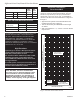
Jefferson Direct Vent /Natural Vent Gas Heater 4 2 6 1a 7 5 3 1b 1c 11 1d 9 12 8 1e 10 16 14 18 15 17 20a,b 22 19 30 33 24 25 26 31 29 23 21 34 32 27 35 37 C E EM NT 36 40 CFM Corporation reserves the right to make changes in design, materials, specifications, prices and discontinue colors and products at any time, without notice. Jefferson Direct Vent/Natural Vent Gas Heater ���� Model: JDVBRN Ref. 1. 1a. 1b. 1c. 1d. 1e. 2. 3. 4. 5. 6.
Jefferson Direct Vent/Natural Vent Gas Heater Jefferson Direct Vent/Natural Vent Gas Heater Model: JDVBRN Ref. Descripción 7. 8. 9. 10. 11. 12. 13. 14. 15. 16. 17. 18. 19. 20a. 20b. 21. 22. Right End Front Glass Glass Frame Assembly Gasket, Glass - Med. Knit Door, Control Door Magnet (not shown) Leg Front Handle Assembly Handle Damper - Maplewood - Blk Burner Housing Assembly NG/LP Grate, Burner Manifold Assembly Valve - Nova SIT820.662 RN Valve - Nova SIT820.653 RP Pilot Assembly 3-Way N/DV RN 0.199.
Jefferson Direct Vent /Natural Vent Gas Heater Optional Accessories Fan Kits FK28 Fan The FK28 fan helps distribute heated air from within the firebox out into the room. The fan is controlled by a snapstat that turns power on and off as the firebox temperature rises above and falls below a preset temperature. A rheostat provides for variable fan speeds. Specifications 115 Volt / 60Hz / .
Jefferson Direct Vent/Natural Vent Gas Heater 3636 30004177
Jefferson Direct Vent /Natural Vent Gas Heater 30004177 37
Jefferson Direct Vent/Natural Vent Gas Heater 3838 30004177
Jefferson Direct Vent /Natural Vent Gas Heater CFM CORPORATION WARRANTY FOR ALL CENTURY GAS PRODUCTS TWO YEAR LIMITED WARRANTY This Warranty gives you specific legal rights and you may also have other rights that vary in each State or Province. 1.
Efficiency Ratings Model JDVBRN JDVBRP EnerGuide Ratings Fireplace Efficiency (%) 60.7 60.7 CFM Corporation 2695 Meadowvale Blvd. • Mississauga, Ontario, Canada L5N 8A3 800-668-5323 • www.cfmcorp.