
Operating Manual Direct Vent/Natural Vent Gas Heater Jefferson

7
Jefferson Direct Vent /Natural Vent Gas Heater
30004177
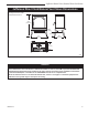
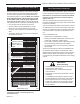
Hearth Requirements
The Jefferson Heater must be installed on rigid flooring.
When the heater is installed directly on any combustible
surface other than wood flooring, a metal or wood panel
extending the full width and depth of the unit must be
used as the hearth. There are no other hearth require-
ments.
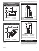
Parallel Installation:
Minimum Clearance and Flue Centerline,
Direct Vent and Natural Vent
ST128a
FDV28
flue centerline
12/3/99 djt
C
L
C
L
B
D
C
A
Stove Clearances A: 4” (102 mm)
B: 4” (102 mm)
Pipe Centerlines C: 14¹⁄₂” (369 mm)
D: 9” (229 mm)
ST128a
Fig. 3 Parallel installation, minimum back and side clear-
ances and flue centerlines.
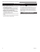
Corner Installation: Minimum Clearance and
Flue Centerline, Direct Vent & Natural Vent
ST129b
Stardance
corner specs
9/28/00 djt
A
A
B
B
Stove Clearance A: 4: (102 mm)
Pipe Centerline B: 14³⁄₄” (375 mm)
ST129b
Fig. 4 Corner installation, minimum corner clearance and flue
centerline.
Wall Centerline from Floor
ST131a
wall thimble
12/3/99 djt
A
Effective Minimum
Wall Thimble 58
¹⁄₄” (1480 mm) (CFM Pipe)
Centerline 54³⁄₄” (1378 mm) (Simpson Duravent Pipe)
ST131a
Fig. 5 Minimum wall thimble centerline.
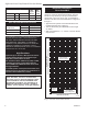
Wall and Ceiling Clearances
A
C
D
ST101a
Direct Vent
Min. Clrnc
12/3/99 djt
B
A: Rear Wall 4” (102 mm)
B: Min. Clearance 43
¹⁄₂” (1105 mm)*
C: Min. Alcove Height 72” (1830 mm)*
D: Max. Alcove Depth 48” (1220 mm)
Sidewall clearance 4” (102 mm)
ST101a
* needed for installing DuraVent Minimum Vent Kit #2792
or CFM Minimum Vent Kit #7TFSDVSK
Fig. 6 Dimensions and clearances to ceiling or alcove.