
Product Manual


TEST PROCUDURE
All Models
Connect the temporary power distribution unit to
an appropriate power source.
1. Verify all circuit breakers are in the “on”
position.
2. Push the test button on the individual GFCI
module. The unit should trip.
3. Push the reset button. The indicator light
should come on.
4. Repeat steps 2 & 3 for the remaining three (3)
modules.
TROUBLE SHOOTING
The GFCI Modules within the temporary power
distribution unit will trip whenever one or more of
the following abnormal conditions exist in the line
(supply) side circuit:
1. Either line (hot) conductor is transposed with
the neutral conductor.
2. Either line (hot) conductor is open
(disconnected)
3. There is an excessive voltage imbalance
between line 1 and line 2 circuits. This may be
the result of an open neutral conductor in the
supply circuit.
When the abnormal condition(s) in the supply
circuit is corrected, the unit may be reset for
normal use by completely removing and then
reapplying line power. It is recommended that
the GFCI test procedure be repeated at this time.
When a GFCI module trips, attempt to reset it by
pressing the reset switch, being careful to look
for possible danger to personnel. If the module
resets, the fault was momentary and has
cleared. If it trips again immediately, the fault is
still present and the GFCI module is performing
its safety function. To locate the fault, disconnect
all loads and again try pressing the reset switch.
The module should reset. Reconnect the loads
one at a time. The module will trip when the
faulted load is reconnected. Inspect all tools,
appliances and extension cords in the faulted
load circuit, repairing or replacing any that are
not in good condition. NOTE: Tripping of a circuit
breaker in these models can only result from an
overload or short circuit condition in its individual
load circuit. When the fault in the load circuit is
corrected or removed, the circuit breaker can be
reset for normal use by switching handles to
“OFF” position and then to the “ON” position.
NUISANCE TRIPPING
All cables have some capacitive leakage. In a
120 volt system, there is a limit to the length of
cable which can be run before sufficient leakage
to ground will build up causing a GFCI to trip.
Individual 120 volt branch circuit load cords
should be limited to 250 feet in length.
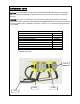
APPLICATION NOTES
Enclosure is a NEMA Type 3R; enclosures are
intended for use outdoors to protect the enclosed
equipment against windblown dust and water
and to provide for its operation when the
enclosure is covered by external ice or sleet.
HIGH VOLTAGE LIGHT
An illuminated high voltage light indicates the
input wiring is incorrect; check the power source.
CONTACT MONITOR LIGHT
The red monitor light is a welded contact
indicator. If the monitor light is on with the unit
tripped, it indicates the contact is welded, and
the unit should be replaced immediately -- there
is no GFCI protection. When the TEST button is
pressed, both the POWER light and MONITOR
light should go out, and come back on when the
RESET button is pressed.