™ 206 Remote Control System User Manual DN: U024.2-SmaRT_206_SYS-R 2008 Cervis, Inc.
SmaRT 206 This document is the property of Cervis, Inc. and cannot be copied, modified, e-mailed, or reproduced without the express prior written consent of Cervis, Inc. Cervis, Inc. reserves the right to change this manual or edit, delete, or modify any information without prior notification. FCC Statements 15.19 – Two Part Warning This device complies with Part 15 of the FCC rules.
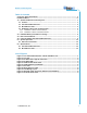
Remote Control System Table of Contents Cervis Inc. Safety Precautions ................................................................................................... ii Definitions/Notes ......................................................................................................................... iii 1.0 SmaRT 206 Remote Control System .................................................................................. 1 1.1 Features ...........................................................
SmaRT 206 Cervis Inc. Safety Precautions Read and follow all instructions. Failure to abide by Safety Precautions may result in equipment failure, loss of authority to operate the equipment, and personal injury. Use and maintain proper wiring. Follow equipment manufacturer instructions. Improper, loose, and frayed wiring can cause system failure, equipment damage, and intermittent operation.
Remote Control System Definitions/Notes Association SmaRT configuration method using a series of specific remote unit button presses to establish a communication link between a SmaRT Handheld and a SmaRT Base Unit. DSSS Direct sequence spread spectrum; an advance wireless communication technology. Disassociation Dissolution of all established communication links between handhelds and a base unit.
SmaRT 206 This page is intentionally left blank. iv U024.
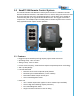
1.0 SmaRT 206 Remote Control System The standard SmaRT 206 Remote Control System consists of a 6-Button PTO-206 wireless handheld transmitter, a BU-206F base unit, and the wiring harness that is used to connect the base unit to the controlled apparatus. A single base unit is capable of communicating with up to eight PTO-206 Handheld units. The rugged construction, compact size, and multiple output versatility allow for SmaRT Systems to be used for many applications that require remote operation. Figure 1.
SmaRT 206 1.2 PTO-206 Handheld Remote The SmaRT PTO-206 Handheld Remote features a handheld-to-base unit 300 ft. (100m) communication range providing six function press-to-operate (PTO) control. Using direct sequence spread spectrum (DSSS) wireless technology at 2.4GHz, the handheld unit provides a robust link with a base unit in congested radio environments. SmaRT handheld units feature seamless association to a SmaRT BU-206F Base Unit without the need to open either case.
Remote Control System 1.3 BU-206F Base Unit The SmaRT BU-206F Base Unit features six FET, 24A max high-side switching outputs. It accepts an input operating voltage range from +9 to +16VDC for the standard base unit. An optional BU-206F using +16 to +32VDC input operating voltages is available. Using Direct Sequence Spread Spectrum (DSSS) wireless technology at 2.
SmaRT 206 1.4 Handheld ↔ Base Unit Communication A standard SmaRT 206 System comes with one PTO-206 Handheld Remote and one BU-206F Base Unit, but each BU-206F is capable of communicating with up to eight PTO-206 Handheld Remotes. Each handheld must first establish a communications link with the base unit before the base unit will recognize the handheld unit. This process is called Association. 1.4.
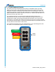
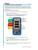
Remote Control System 6. Press and hold the Association button (see Figure 5 below). The RX extinguishes, the TX glows steady green, and the LINK LED glows steady amber. 7. Apply power to the base unit while continuing to hold the Association button. The base unit and handheld begin Association to establish a communication link. Once the process is complete, the amber LINK LED extinguishes, the RX begins flashing red, and the TX glows steady green and remains so until the Association button is released. 8.
SmaRT 206 8. Release the Disassociate button. The RX LED extinguishes, the TX LED flashes green for a brief time and then it too extinguishes. The SmaRT BU-206F Base Unit will not communicate with any handheld remote units. A handheld remote must use the Association Procedure (1.4.1) to re-establish a communication link with the base unit. 2.0 Handheld Battery Installation or Change The SmaRT handheld unit is powered by three size AAA batteries.
Remote Control System 3.0 Base Unit Installation CAUTION Make sure the machine on which the base unit is to be attached is disabled during installation. Use the configuration diagrams supplied by Cervis to guide you in mounting the base unit and connecting your wiring harness. Mounting of the base unit is left much to your discretion with the following guidelines: • Make sure that the configuration diagrams supplied with the system are available. Keep them where they can be easily accessed when needed.
SmaRT 206 Note: Harness cable wires are individually marked on the insulator of each wire. Figure 8. Wiring Harness Cable Figure 9. Field Wiring Layout CAUTION Be sure the ends of all unused wires are insulated when making your connections to protect against short circuits. Figure 10. BU-206F Cable Connecter (Enhanced Pin Numbers) 8 U024.
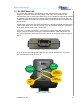
Remote Control System 4.0 Using the SmaRT PTO-206 Handheld Remote The front panel of the SmaRT PTO-206 Handheld Remote has six (6) push-to-operate buttons and three (3) diagnostic LEDs. PTO buttons 1 and 2 have dual functions as described in Figure 11. ASSOCIATE to base unit DISASSOCIATE from base unit TX Output 1 Output 2 RX Output 3 Output 4 LINK Output 5 Output 6 Figure 11. PTO-206 Front Panel 2008 Cervis, Inc.
SmaRT 206 5.0 System Operation The PTO-206 Handheld Remote buttons are push-to-operate only. Each button is dedicated to its assigned, hardwired BU-206F output driven by the base unit. The output is only controlled when the appropriate button is pressed and held. Once the button is released, the BU-206F output under control stops, and the BU-206F waits for the next command sent by the PTO-206. The following instructions outline what is needed for use of and how to use the SmaRT 206 Remote Control System.
Remote Control System 8. Release Button 1. The RX LED goes out, the TX LED briefly flashes green, and then it goes out. 9. Test that each push-to-operate (PTO) button operates the output to which it is assigned. When a PTO button is pressed, its assigned base unit output is active and the base unit Out LED should glow green for as long as the output is active. When the PTO button is released, the output becomes inactive, and the base unit Out LED goes out.
SmaRT 206 6.0 Specifications 6.1 PTO-206 Handheld Remote Table 1 - Handheld Specifications Item Description Power Vin +3.6V to +4.5V Batteries Auto-shutdown Three (3) AAA 3 Sec. of button inactivity TOperating -20°C to 55°C Environment (-4°F to 131°F) TStorage Radio Enclosure Humidity -40°C to 55°C (-40°F to 131°F) 0 to 100% Frequency 2405-2480MHz RF Signal 2mW License License free Modulation Antenna DSSS Internal Dimensions mm: 136.38 x 67.96 x 28.42 inches: 5.37 x 2.68 x 0.
Remote Control System 6.2 BU-206F Base Unit Table 2 - Base Unit Specifications Item Description Power Vin +9 to +16VDC Vin (optional) +16 to +32VDC P operating Environment TOperating 1W nominal -20°C to 70°C (-4°F to 158°F) TStorage -40°C to 85°C (-40°F to 185°F) Humidity 0 to 100% Vibration/Shock IEC60068-2-6 10Hz to 150Hz @ 1.0g peak acceleration 10.
SmaRT 206 Cervis, Inc. Visit our Web site at: www.cervisinc.com and are trademarks of CERVIS, Inc. 2008 Cervis, Inc. All rights reserved. Content is subject to change without notice. 14 U024.
Remote Control System 2008 Cervis, Inc.