
User's Manual
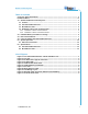

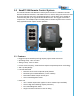
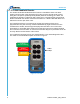
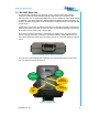
Table Of Contents

Remote Control System
2008 Cervis, Inc.
i
Table of Contents
Cervis Inc. Safety Precautions ................................................................................................... ii
Definitions/Notes ......................................................................................................................... iii
1.0 SmaRT 206 Remote Control System .................................................................................. 1
1.1 Features ............................................................................................................................. 1
1.2 PTO-206 Handheld Remote .............................................................................................. 2
1.3 BU-206F Base Unit ............................................................................................................ 3
1.4 Handheld ↔ Base Unit Communication ........................................................................ 4
1.4.1 Handheld ↔ Base Unit Association ............................................................................ 4
1.4.2 Handheld ↔ Base Unit Disassociation ....................................................................... 5
2.0 Handheld Battery Installation or Change .......................................................................... 6
3.0 Base Unit Installation........................................................................................................... 7
4.0 Using the SmaRT PTO-206 Handheld Remote .................................................................. 9
5.0 System Operation .............................................................................................................. 10
5.1 Initial Use Instructions ................................................................................................... 10
6.0 Specifications ..................................................................................................................... 12
6.1 PTO-206 Handheld Remote ............................................................................................ 12
6.2 BU-206F Base Unit .......................................................................................................... 13
List of Figures
Figure 1. PTO-206 Handheld Remote and BU-206F Base Unit .................................................. 1
Figure 2. PTO-206 ........................................................................................................................... 2
Figure 3. BU-206F Twelve (12) Pin Connector ............................................................................ 3
Figure 4. BU-206F LEDs ................................................................................................................ 3
Figure 5. Handheld PTO Front Panel ........................................................................................... 4
Figure 6. Handheld Battery Installation ....................................................................................... 6
Figure 7. Base Unit ......................................................................................................................... 7
Figure 8. Wiring Harness Cable .................................................................................................... 8
Figure 9. Field Wiring Layout ........................................................................................................ 8
Figure 10. BU-206F Cable Connecter (Enhanced Pin Numbers) ............................................... 8
Figure 11. PTO-206 Front Panel .................................................................................................... 9