JuiceBox Pro User Manual
Table of contents Welcome to JuiceBox Pro 3 Package Contents 3 Required Tools 3 Installation 4 Installation Prerequisites 4 Installation 5 Load Balancing 8 Locking Your JuiceBox 9 Wi-Fi Setup 9 JuiceBox Configuration 11 Configure JuiceBox Using Bluetooth Connectivity 11 Configure JuiceBox Using Wi-Fi Connectivity 16 Specifications 21 Characteristics 21 Connectivity 21 Dimensions 22 LED Indicator 24 Using the Dashboard 25 Enterprise Dashboard Manual 25 Business
Welcome to JuiceBox Pro Package Contents > JuiceBox NOTE In some markets, JuiceBox arrives secured to a cable holder that includes keys. > Wall bracket > 2 wall bracket screws (#10 self-tapping Phillips head wood screws) > 2 screws to hang JuiceBox onto wall bracket (#10-32 Phillips head machine screws) > 1 RFID card (except 80A) Required Tools > Phillips Screwdriver (No.
Installation Installation Prerequisites OVERVIEW JuiceBox requires either a hardwired electrical connection or a NEMA 14-50 outlet. The JuiceBox power supply must be connected to a non-GFI circuit breaker that is rated for at least 125% of the device's continuous load. NOTE Ensure that all power connection wiring conforms to the rules and regulations of any national and local codes.
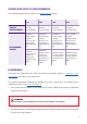
WIRING AND CIRCUIT REQUIREMENTS For additional specifications, refer to the Specifications section. CIRCUIT REQUIREMENTS RECOMMEND WIRING 32A 40A 48A 80A 40 Amp 2 pole breaker 50 Amp 2 pole breaker 60 Amp 2 pole breaker 100 Amp 2 pole breaker #8AWG or larger gauge copper wires for the conductors (NEC 625.17(A) (2) #6AWG or larger gauge copper wires for the conductors (NEC 625.17(A) (2) #4AWG or larger gauge copper wires for the conductors (NEC 625.
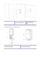
Version with cable holder Version without cable holder 3. Insert the enclosure screws into the enclosure, as shown. Tighten the screws until approximately 2 mm of thread are visible.
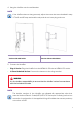
4. Hang the JuiceBox onto the wall bracket. NOTE If the JuiceBox does not hang securely, adjust the screws that were installed in step 3. The 48 and 80 amp are hardwire only and do not have a plug as shown. Version with cable holder Version without cable holder 5. Connect the JuiceBox: > Plug-In Version: Plug the JuiceBox into the NEMA 14-50 outlet or NEMA 6-50 outlet. > 1-Phase Hardwired Version: Connect the harness to the wiring terminal.
32A/40A 48A 80A L1 (Black) 8 AWG 6 AWG 3 AWG L2 (Red) 8 AWG 6 AWG 3 AWG Ground (Green) 8 AWG (THHN) 8 AWG (THHN) 6 AWG (THHN) 6. Turn on the circuit breaker that supplies power to the NEMA 14-50 outlet, NEMA 6-50 outlet, or hardwired electrical connection. Load Balancing > Load balance to Circuit only. > Load balance to panel is NOT recommended. NOTE Balancing to the panel or location can be done on a system that would otherwise work safely on its own.
Locking Your JuiceBox After installing your JuiceBox, use the included keys to lock the JuiceBox to the wall frame. Wi-Fi Setup 1. Reset the circuit breaker that supplies power to the JuiceBox. NOTE The following steps must be completed within 2 minutes of reconnecting power to the JuiceBox. The JuiceBox will remain in setup mode for 4 minutes. 2. Open Wi-Fi settings on your personal device. Connect to the "JuiceBox-###" or "JuiceNet-###" WiFi network.
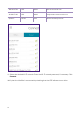
138.91.137.23 UDP 8042 jbv1.emotorwerks.com 40.118.171.20 UDP 8042 emwjuicebox.emotorwerks.com dynamic HTTPS 443 device-backend.juice.net 4. Select the desired Wi-Fi network. Enter the Wi-Fi network password, if necessary. Click Connect. Verify that the JuiceBox is connected by checking that the LED indicator turns white.
JuiceBox Configuration For best results, perform this procedure while standing within 5 ft (1.6m) of the JuiceBox. Configure JuiceBox Using Bluetooth Connectivity *REQUIRES FIRMWARE 1.0.46 OR LATER 1. Download and install the “JuiceConfigure” app onto your mobile device. Video walkthrough of this section 2. Open the JuiceConfigure app. NOTE Make sure your phone and JuiceBox’s Bluetooth connection is enabled before starting to be able to configure Wi-Fi for your charger.
3. Select START CONFIGURATION. 4. Follow the onscreen instructions to proceed to JuiceBox configuration.
5. Chargers are scanned and listed on the screen. Select Pair to configure the charger. 6. Your JuiceBox is now connected to your account.
7. Wi-Fi networks are scanned and listed on the screen. Select the network you want to connect your JuiceBox to. 8. Enter the password of the selected Wi-Fi network and select Connect charger to Wi-Fi.
9. The JuiceBox is connected to your account. Select CONTINUE. 10. In the configuration screen, set the maximum current for charger at which you want to charge your vehicle, then select SAVE. NOTE After connecting, JuiceBox checks its firmware version and performs any necessary updates. Wait 10 minutes before plugging in a vehicle.
Configure JuiceBox Using Wi-Fi Connectivity 1. Download and install the “JuiceConfigure” app onto your mobile device. Video walkthrough of this section 2. Open the JuiceConfigure app. 3. Select START CONFIGURATION.
4. Select Configure via Wifi. 5. Have the Wi-Fi network password ready, then select NEXT. NOTE If the JuiceBox is already power on before this step, disconnect it from power and re-connect again before proceeding. NOTE After powering the JuiceBox, complete the steps 6 through 9 within 2 minutes.
6. Navigate to the Wi-Fi settings on your mobile device. Connect to the “JuiceBox-###” or “JuiceNet-###” Wi-Fi network. If the network requires a password, use the password “GoElectric” (case-sensitive). NOTE The actual name of the network varies by device, such as “JuiceBox-123”. 7. Return to the JuiceConfigure app.
8. In the JuiceConfigure app, select the preferred local Wi-Fi network. 9. Enter the Wi-Fi network password, if necessary, then select CONNECT CHARGER TO WI-FI.
10. The app connects the JuiceBox to the Wi-Fi network, then select CONTINUE. 11. You did it! The JuiceBox is now online and ready to charge. NOTE After connecting, JuiceBox checks its firmware version and performs any necessary updates. Wait 10 minutes before plugging in a vehicle.
Specifications Characteristics 32A max: Up to 7.7 kW, 32A, 1-phase 40A max: Up to 9.6 kW, 40A, 1-phase OUTPUT POWER 48A max: Up to 11.5 kW, 48A, 1-phase 80A max: Up to 19.2 kW, 80A, 1-phase INPUT VOLTAGE 208 or 240 VAC CHARGING MODE Mode 3 LEDS Dynamic LEDs displaying charging status IP67 PROTECTION AC 20mA Ground Fault Detection TEMPERATURE RANGE STANDARDS AND CERTIFICATIONS From -40°C to +60°C IEC 61851-1 UL Certified Connectivity WIFI IEE 802.11b/g/n 2.
Dimensions 22
LED Indicator COLOR PATTERN MEANING Orange Pulsing Powering on Blue Flashing Setup Mode Yellow Flashing Vehicle plugged in, charging ended or suspended All white patterns indicate that unit is online Solid Ready to charge 1 Flash + beep* RFID card swiped Flashing Ready to charge, vehicle not plugged in White All purple patterns indicate that unit is offline Solid Ready to charge 1 Flash + beep* RFID card swiped Flashing Ready to charge, vehicle not plugged in Solid* Vehicle no long
Using the Dashboard Enterprise Dashboard Manual To access the JuiceNet Enterprise documentation and FAQs, log into your Enterprise account. Business Dashboard Manual To access the JuiceNet Enterprise documentation and FAQs, log into your Business account. RFID Cards RFID Reader IP ADDRESS PROTOCOL PORTS FQDN dynamic HTTPS 443 directory-api.emotorwerks.com dynamic HTTPS 443 ota.zentri.com dynamic HTTPS 443 dms.zentri.com 104.40.90.102 UDP 8042 jbv1.emotorwerks.com 40.118.171.
Important Safety Information Read all safety information before installing this product. WARNING: This device should be supervised when used around children. WARNING: Do not put fingers into the electric vehicle connector. WARNING: Do not use this product if the flexible power cord is frayed, has broken insulation, or shows any other signs of damage. WARNING: For use with electric vehicles only. WARNING: Do not use this device with an extension cord.
> Reorient or relocate the receiving antenna. > Increase the separation between the equipment and receiver. > Connect the equipment into an outlet on a circuit different from that to which the receiver is connected. > Consult the dealer or an experienced radio/TV technician for help. WARNING Changes or modifications not expressly approved by the party responsible for compliance could void the user’s authority to operate the equipment.