Rack Conveyor Dishwasher Installation/Operation Manual with Service Replacement Parts Rack Conveyor Dishwasher CH-44, MD-44 44" Single Tank with built-in electric booster CH-66, MD-66 44" Single Tank with 22" Prewash with built-in electric booster International Models I-44 44" Single Tank with built-in electric booster Single Tank Model CH-44, MD-44, I-44 I-66 44" Single Tank with 22" Prewash with built-in electric booster Single Tank w/Prewash Model CH-66, MD-66, I-66 Dishwasher serial no.
For future reference, record your dishwasher information in the box below.
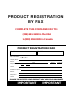
REGISTER YOUR PRODUCT ONLINE Make sure you are connected to the internet, then enter the address below: IN THE USA CHAMPION http://www.championindustries.com/register MOYER DIEBEL http://www.moyerdiebel.com/register IN CANADA CHAMPION AND MOYER DIEBEL http://www.championindustries.
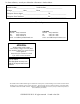
PRODUCT REGISTRATION BY FAX COMPLETE THIS FORM AND FAX TO: (336) 661-1660 in the USA 1-(800) 204-0109 in Canada PRODUCT REGISTRATION CARD Serial # Model Date of Installation: Company Name: Address: Telephone #: ( ) --- (Street) Province Postal Code Contact: Installation Company: Address: Telephone #: Contact: FAILURE TO REGISTER YOUR PRODUCT MAY VOID YOUR WARRANTY IMPORTANT IMPORTANT
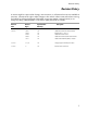
Revision History Revision History A revision might be a part number change, new instructions, or information that was not available at print time. We reserve the right to make changes to this manual without notice and without incurring any liability by making the changes. Dishwasher owners may request a revised manual, at no charge, by calling (800) 858-4477 in the USA or (800) 263-5798 in Canada. Revision Date Revised Serial Number Pages Effectivity Description 4.1.
Limited Warranty LIMITED WARRANTY Champion Industries Inc. and Moyer Deibel (herein referred to as"The Companies"), 3765 Champion Boulevard, WinstonSalem, North Carolina 27105, and P.O. Box 301, 2674 N. Service Road, Jordan Station, Canada, L0R 1S0, warrants machines, and parts, as set out below.
Table of Contents Table of Contents Rack Conveyor Dishwashers Models CH-44, MD-44, I-44 and CH-66, MD-66 and I-66 Revisions to this manual........................................................................................ i Limited Warranty................................................................................................. ii Model Descriptions.............................................................................................. iv Installation.........................
Model Descriptions Model Descriptions Models CH-44 and MD-44 Electric high temperature single tank rack conveyor dishwasher with a built-in electric booster in 40°F/22°C rise or optional 70°F/39°C rise. This model's direction of operation is convertible in the field. Models CH-66 and MD-66 Electric high temperature single tank with prewash tank rack conveyor dishwasher with a built-in electric booster in 40°F/22°C rise or optional 70°F/39°C rise.
Installation Receiving 1. Inspect the outside of the dishwasher carton for signs of damage. 2. Remove the carton and inspect the dishwasher for damage. 3. Check for any options or accessories that may have shipped with your dishwasher. 4. Turn to the front of this manual and follow the instructions to register your product online or by fax. NOTE: The installation of your dishwasher must be performed by qualified service personnel. Problems due to improper installation are not covered by the Warranty.
Installation Utilities Hot Water Connections NOTE: Only qualified personnel should make dishwasher plumbing connections. Connections must meet local plumbing and sanitary codes. Improper installation is not covered be the dishwasher warranty. Hot Water Requirements: 1. Connect a 3/4" NPT hot water supply line to the line strainer located at the top rear of the dishwasher. A water hardness of 3 grains/gal (US) [51.3 mg/L] or less is recommended. 2.
Installation Drain Connections 1. The 1-1/2" drain line was removed and packed inside the dishwasher prior to shipping. Install the drain line once the dishwasher has been placed in its final location. 2. Connect the 1-1/2" NPT drain line to above a drain sink or to a 1-1/2" or larger drain line connection. 3. Observe all local plumbing and sanitary codes when installing. Ventilation Connections 1. DO NOT VENT THE DISHWASHER INTO WALLS, CEILINGS OR ENCLOSED PLACES. 2.
Installation Electrical Connections WARNING: Electrocution or serious injury may result when working on an energized circuit. Disconnect power at the main breaker or service disconnect switch before working on the circuit. Lock-out and tag the breaker to indicate that work is being performed on the circuit.
Installation Electrical Connections (continued) Motor Rotation 1. Check the converyor drive motor to ensure it rotates in the correct direction. The motor shaft must rotate in a counterclockwise direction when viewed from the rear. 2. The dishwasher motors are pased together; therefore, if the conveyor motor rotation is correct then the pumo motors will also be correct. 3.
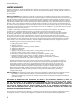
Installation Chemical Signal Connections 1. Use a qualified detergent/chemical supplier for detergent/chemical and dispensing equipment needs. 2. Labeled detergent control circuit connection terminals are provided in the control cabinet for detergent and rinse agent/sanitizer dispensing equipment (supplied by others). 3. The illustration at right, shows the terminal board for the machine. 4. The signal connection points include: • Detergent signal 120VAC, 1A max load.
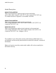
Installation Curtain Locations 1. Refer to the illustrations below and hang the curtains as shown. J-hooks are located in the corners of each section to accept the curtain rods. • Standard long curtains • Standard medium curtains • Standard short curtain 24" x 20-1/4" 24" x 13-/14" 24" x 6-1/4" 2. Make sure the that the short flaps of the curtains face the load end of the dishwasher.
Installation Door Safety Switches Dishwasher access doors are equipped with a door safety switch that automatically stops the dishwasher pumps and conveyor drive if a door is raised while the dishwasher is running. In addition, the dishwasher will not start if a door is left open. 1. If the dishwasher is running and a door is raised, then lighted GREEN START pushbutton goes out and the pumps and conveyor drive stop. 2. Check the interior of the dishwasher for any dish racks still in the machine.
Installation Scrap Screens 1. All models have scrap screens in the top of the wash tank. Install four scrap screens in the wash tank making sure they fit securely without large gaps between them. All models have four scrap screens in the wash tank. 2. The CH-66 and the MD-66 models have a prewash tank containing a single large scrap screen which extends from front to back in the prewash tank.
Installation Installing the Lower Spray arm Assembly 1. The lower spray arm assembly is connected to the rear wall of the wash tank. 2. The spray arm o-ring makes a water-tight seal when the spray arm is properly seated. Spray Arm O-ring Spray Arm Guide 10 3. Slide the lower arm into place making sure the spray arm is fully back and contacting the spray arm o-ring. 4.
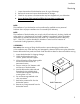
Installation Installing the Upper Spray Arm Assembly The upper wash arm assembly is suspended from the top of the dishwasher hood interior by front and rear supports. Follow the instructions and illustrations below to install the upper wash arm assembly. Wash Arm Connection Flange Pin Connection Flange Rear Support Front Support Upper Wash Arm Assembly Upper wash arm assembly shown installed. (Note that the Wash Arm Connection Flange Pin is seated in the Connection Flange.
Installation Installing the Upper Spray Arm Assembly (continued) 1. Upper Wash Arm Rear Guide Pin The rear guide pin is attached to the rear of the upper wash arm. It mates with the upper wash arm rear support. 2. Connection Flange Pins The connection flange pins are welded to the sides of the upper wash arm. These pins mate with two slots in the connection flange to hold the wash arm in place when installed. 3.
Installation Installing the Upper Spray Arm Assembly Installation Upper Wash Arm Front Supports Upper Wash Arm Rear Support 1. 2 1 Connection Flange Upper Wash Arm Assembly The upper wash arm assembly is shown resting on the upper wash arm rear support as it slides toward the connection flange. Open the dishwasher access doors and check the location and condition of the connection flange o-ring. Replace the o-ring if it is worn or damaged.
Installation Installing the Curtains J-hook Short Curtain Long Curtain Medium Curtain Curtain Installation Shown at the Final Rinse End of the Dishwasher 1. Curtain are equipped with curtain rods. The rods are hung on J-hooks located in the top of the dishwasher. 2. Make sure that the short flaps on the curtains face the load end of the dishwasher. 3. Refer to page 7, Curtain Locations, for additional information on curtain placement.
Installation Check List 1. Remove white protective film from the dishwasher exterior. 2. Install lower panels to the dishwasher. 3. Remove any foreign material from inside of the machine. 4. Check dishwasher drain/overflows are closed and in securely seated. 5. Install scrap screens, spray arms. 6. Turn main utilities to the dishwasher ON. (Power, water). 7. Make sure doors are closed. 8. Turn dishwasher power switch ON. Machine fills with water and tank heat comes on. 9.
Initial Start-Up Control Panel Operation - CH-44, CH-66 The final rinse pressure gauge is located behind the control panel. The top-mounted control panel contains the Power ON/OFF switch, start push button, stop push button, and the water temperature gauges for the wash tank and the final rinse. The function of these controls are: A Final Rinse Pressure Gauge - Indicates the flowing water pressure during the final rinse. Proper reading is 20-22 PSI.
Operation MD-44, MD-66 - Control Panel Operation The final rinse pressure gauge is located behind the control panel. The top-mounted control panel contains the Power ON/OFF switch, start push button, stop push button, and the water temperature gauges for the wash tank and the final rinse. The function of these controls are: A Final Rinse Pressure Gauge - Indicates the flowing water pressure during the final rinse. Proper reading is 20-22 PSI.
Operation Operation 2 1 Detergent Rinse-aid Check the chemical containers and refill as necessary. 3 Close the doors. 4 ON POWER OFF Turn drain handle clockwise to close the drains. 5 ON START STOP Push START switch. The green light illuminates. The machine fills with water and the tank heat comes on. 18 Flip power switch UP to the ON position.
Operation Operation 6 7 Open 160°F/71°C 80 60 40 0 60 80 100 20 8 Prescrap & load wares into dish racks. Plates and glasses go in peg rack, cups and bowls go in a flat rack. Place silverware in a single layer in flat rack. 0 22 Wash Temperature Closed If the drain is open or the fill runs for more 10 minutes then the dishwasher shuts down & the green light blinks on and off. Close the drain or check the fill, then push the power switch off and back on to reset.
Operation Operation (continued) 11 180-195°F 82-91°C 120 100 80 60 40 0 20 60 180 20 140 160 40 80 200 10 100 0 22 Final Rinse Temperature The dishwasher pumps and drive runs 90 seconds after the rack enters the machine. Loading additional racks before the first rack exits the machine resets the timer. 12 ON STOP Push the STOP switch to stop the pumps and the drive. The green light goes out. Push the START switch and insert a dish rack to restart operation.
Cleaning Cleaning Cleaning your dishwasher is the best maintenance you can do.The cleaning intervals below are the minimum requirements for most dishwashers.You may need to clean your dishwasher more often when washing heavily soiled wares or during long periods of continuous operation. Daily or every 2 hours of operation 1. Turn power switch to OFF. 2. Pull drain lever(s) to drain water. Remove scrap screens and scrap baskets. Clean inside of the tanks and flush with clean water.
Cleaning Cleaning (continued) 2 1 ON POWER OFF Flip power switch down to the OFF position. 3 Open doors. 5 Remove the upper wash arm assemblies and flush clean in a sink. 22 Turn drain handle counter-clockwise to the vertical position to drain the tanks. 4 Remove curtain assemblies and rinse clean in a sink. 6 Remove lower wash arm assemblies and flush clean in a sink.
Cleaning 7 8 O-ring Remove the end plugs on each wash arm and flush the pipes clean. 9 Check the o-ring on each plug and replace if necessary. 10 For Prewash Unit Only Remove the scrap screens and backflush in a sink. Do not strike the screens on hard surfaces. Remove the refuse basket and backflush in a sink. Do not strike the basket on hard surfaces.
Cleaning Cleaning (continued) 11 12 Paper Clip Check the final rinse nozzles and clean with a small paper clip as required. Thoroughly spray the interior of the machine with fresh clean water. 13 14 Pump Intake Screen Heating Element Dual Float Switch Drain Screen Remove the pump intake screen and flush clean in a sink. Check and clean the dual float switch, heating element and drain screen. Wipe the exterior of the machine with mild detergent and soft cloth. DO NOT HOSE DOWN WITH WATER.
De-liming De-liming Lime (scale) deposits are the result of minerals contained in the water feeding the dishwasher and appear as a white haze on the surface of the dishwasher. Severe scaling can appear as a granular deposit. These deposits are the result of the mineral content in the geographic area in which the machine is located. WARNING: Death or injury can result from toxic fume when de-liming agents come in contact with Chlorine Bleach, or other chemicals that contain iodine, bromine, or fluorine.
Maintenance Maintenance Weekly 1. Inspect all water lines for leaks and tighten at joints if required. 2. Clean any detergent residue from the exterior of the machine. 3. Check that the drain/overflow pipes seat tightly in their drains. 4. Clean any accumulated scale from the heating element. 5. Inspect the spray arms for any damage or missing parts. 6. Inspect the final rinse arms for missing parts. 7. Inspect the pawl bar and drive assembly for damage or missing parts. 8.
Troubleshooting Before calling for service check the following conditions. 1. Dishwasher main power and water supply is on. 2. Machine has been assembled correctly. 3. Conveyor is clear of any obstructions. 4. Drains are closed. 5. Screens and pump intake screens are clear. 6. Doors are closed and secure. Condition Cause Solution Dishwasher will not run. Door not closed. Main power OFF. Dishwasher OFF. Dish rack inserted wrong Close door completely. Check breaker on panel. Turn dishwasher ON.
Blank Page This Page Intentionally Left Blank 28
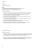
Service Replacement Parts Illustrations Page Control Panel - MD-44, MD-66........................................................................................................... 30 Control Panel - CH-44, I-44, CH-66, I-66............................................................................................. 32 Control Cabinet - All Models.............................................................................................................. 34 Extended Vent Cowls - All Models.................
Control Panel - MD-44, MD-66 1 2 12 11 10 9 9 7 8 1 8 5 3 5 6 30 4
MD-44, MD-66 - Control Panel Item No. Part No. 1 100097 SCREW, TRUSS HD., 10-32 X 1/2" SST 3 2 333533 COVER, CONTROL CABINET 1 3 114768 DECAL 36" CONTROL CABINET 3-HOLE, PW-W-R (MD66) 1 4 114767 DECAL 36" CONTROL CABINET 2-HOLE, W-R (MD44) (not shown) 1 5 107440 THERMOMETER, 8FT. FLANGE (Qty. 1 MD44) (Qty. 3 MD66) A/R 6 113622 THERMOMETER, 4FT. GAS FILLED (Qty.
Control Panel - CH-44, CH-66, I-44, I-66 1 2 10 9 8 1 7 5 3 5 6 32 4
CH-44, CH-66, I-44, I-66 - Control Panel Item No. Part No. Description Qty. 1 100097 SCREW, TRUSS HD., 10-32 X 1/2" SST 3 2 334880 COVER, CONTROL CABINET 1 3 115239 DECAL 36" CONTROL CABINET 3-HOLE, PW-W-R, CH66, I66 1 4 115238 DECAL 36" CONTROL CABINET 2-HOLE, W-R, CH44 (not shown) 1 5 107440 THERMOMETER, 8FT. FLANGE (Qty. 1 CH44, I44) (Qty. 3 CH66,I66) A/R 6 113622 THERMOMETER, 4FT. GAS FILLED (Qty.
34 SIGNAL ONLY 17 1 TABLE LIMIT SWITCH MACHINE RUNNING 2 16 4 3 18 24 19 5 25 27 26 20 6 15 7 14 8 9 21 10 11 22 11 12 11 23 13 Control Cabinet - All Models
All Models - Control Cabinet Item No. 1 2 3 4 --- 5 6 --- 7 --- 8 --- 9 10 11 12 13 --- 14 15 16 17 18 19 20 21 --- 22 --- --- 23 --- --- --- --- --- 24 25 26 27 Part No.
Extended Vent Cowls - All Models 10 9 MD44/MD66 4 5 3 7 2 1 8 CH44/CH66 I44, I66 6 36
All Models - Extended Vent Cowls Item No. Part No. 1 100073 SCREW, 1/4-20 X 1/2" TRUSS HD.
Wash Tank Door, Panels and Curtains - All Models 16 17 27 7 13 4 8 18 4 17 18 21 25 26 10 14 19 18 20 15 22 20 9 12 23 2 1 6 5 22 (L-R Direction Shown) 11 1 38 24 19 3
All Models - Wash Tank Door, Panels and Curtains Item No. Part No. Description Qty. 1 100212 SCREW, 10-32 X 3/4" TRUSS HD. 4 2 108250 ROD, CURTAIN 1 3 109723 CURTAIN, 24" X 6-1/4" (RINSE CURTAIN) 1 4 113691 GUIDE, U-CHANNEL, DOOR 2 5 113720 CURTAIN, 24" X 20-1/4" 2 6 113828 ROD, CURTAIN, 5/16" DIA. X 21-1/2" LG.
Wash Tank Heat, Float Switch, and Scrap Screens - All Models 26 27 25 22 21 28 20 21 (L-R Direction Shown) 28 16 19 2 14 18 12 17 5 See Next Page 2 8 7 C H 23 14 29 To Booster 11 H 10 15 C 9 1 6 4 24 H = High-Limit Thermostat C = Control Thermostat 40 4 13 3
All Models - Wash Tank Heat, Float Switch, and Scrap Screens Item No. Part No.
Wash Tank Junction Box Terminal Block - All Models 1 5 4 6 3 2 1 7 42
All Models - Wash Tank Junction Box Terminal Block Item No. Part No. 1 114519 END BLOCK, E/NS 35N 2 2 114514 TERMINAL, SINGLE, ST 2.5 WH (WHITE) 1 3 114517 TERMINAL, DOUBLE STTB 2.5 4 4 114512 TERMINAL, SINGLE ST 2.5 (GRAY) 2 5 114513 TERMINAL, SINGLE, ST 2.5 BU (BLUE) 6 6 114516 END COVER, SINGLE TERMINAL D-ST 2.5 1 7 114518 END COVER, DOUBLE TERMINAL D-STTB 2.5 1 Description Qty.
Prewash Tank, Door and Curtains - CH-66, I-66, MD-66 16 13 15 19 17 18 12 22 20 33 21 12 14 22 23 25 24 1 19 28 26 32 23 8 27 10 29 9 11 6 7 3 5 14 L-R Direction Shown 44 4 2 31 30
CH-66, I-66, MD-66 - Prewash Tank, Door and Curtains Item No. Part No. Description Qty. 1 100547 LOCKNUT, 1/2" NPT SST 1 2 102376 WASHER, FLAT 5/16" 3 12 108250 ROD, CURTAIN, 5/16" DIA. x 24-5/8" LG. 1 3 104882 WASHER, FLAT .531" X 1.06" X .
Fill Piping - All Models 6 1 25 12 20 3 19 22 18 13 7 28 7 27 3 3 8 8 13 5 5 29 3 3 17 2 28 31 13 32 Refer to pg. 74 for booster hoses.
All Models - Fill Piping Item No. Part No.
Final Rinse Piping - All Models 2 1 6 7 4 5 3 4 5 48
All Models - Final Rinse Piping Item No. Part No. Description Qty.
Prewash Spray Arms - CH-66, I-66, MD-66 14 8 5 3 8 1 6 13 Rear of Hood 9 10 12 4 7 50 2 11
CH-66, I-66, MD-66 - Prewash Spray Arms Item No. Part No. Description Qty.
Wash Spray Arms - All Models 7 10 4 8 2 4 18 14 13 19 8 12 15 20 16 10 1 12 17 5 6 11 3 21 52 8 9 7
All Models - Wash Spray Arms Item No. Part No. Description Qty.
Track Assembly - CH-44, I-44, MD-44 1 10 15 8 6 L-R Direction Shown 4 2 12 11 3 7 5 17 14 9 4 2 1 13 4 2 54 16 6
CH-44, I-44, MD-44 - Track Assembly Item No. Part No. 1 100142 HEX GRIP NUT, 5/16-18 SST CTR LOCK 12 2 100734 BOLT, HEX HEAD 1/4-20 X 1/2" SST 12 3 100764 SCREW, ROUND HD.
Prewash Track Assembly - CH-66, I-66, MD-66 1 8 3 19 18 4 17 2 16 10 4 1 9 11 7 15 12 13 14 5 6 56
CH-66, I-66, MD-66 - Prewash Track Assembly Item No. Part No. Description Qty. 1 100735 BOLT, HEX HEAD 1/4-20 X 5/8" SST 4 2 106014 HEX ACORN PLAIN NUT 1/4-20 SST 4 3 106026 WASHER, FLAT 1/4" SST 4 4 106482 WASHER, LOCK 1/4" SPLIT SST 4 4 100764 SCREW, ROUND HD.
Drive Motor Assembly - All Models 3 1 15 16 7 7 2 4 13 5 13 15 11 7 11 17 9 12 6 8 10 14 58
All Models - Drive Motor Assembly Item No. 1 2 3 4 5 6 7 8 9 10 11 12 13 14 --- 15 16 17 Part No. 0509199 327918 113893 327916 327920 327919 106482 102376 113702 113704 113701 113703 113700 113732 113679 100734 100736 109009 Description DRIVE MOTOR SWITCH BRACKET, MOTOR SWITCH MOUNTING SHEAVE, MOTOR AK51, 5/8" BORE PLATE, DRIVE MOTOR TORQUE BRACKET, 44 MOTOR ASSY.
Conveyor Drive Assembly - All Models 10 1 11 2 3 12 4 13 5 19 6 7 8 9 18 Tank Bottom 21 14 20 22 15 23 19 16 24 20 21 17 24 25 60
All Models - Conveyor Drive Assembly Item No. Part No. Description Qty. 1 202381 ROLLER, CROSSHEAD 1 2 100868 STUD, CROSSHEAD ROLLER 1 3 107089 NUT, JAM 1/2-13 1 4 206300 CRANK, RACK ARM 1 5 206301 SHAFT, 5/8" DIA. X 9" LG.
Pump/Motor Assembly - All Models 1 2 3 62
All Models - Pump/Motor Assembly For Models: CH-44, CH-66, MD-44, MD-66 Item No. 1 Part No. 114347 Description PUMP/MOTOR ASSEMBLY (INCLUDES ITEMS 2-3) Qty. 1 208-240/460/60/3 2HP 2 108002 PUMP SEAL ASSEMBLY 1 3 114793 IMPELLER, 3.78" OD, COMPOSITE MTL 1 For International Models: I-44, I-66 Item No. 1 Part No.
Pump Installation - CH-44, I-44, MD-44 10 13 16 11 12 Tank 3 Wash 5 5 4 9 6 1 15 14 2 7 64
CH-44, I-44, MD-44 - Pump Installation Item No. Part No. Description Qty. 1 100154 HEX PLAIN NUT, 5/16-18 SST 4 2 100739 BOLT, HEX HD., 5/16-18 X 3/4" SST 4 3 100740 BOLT, HEX HD.
66 Prewash 12 4 3 10 1 8 6 13 4 6 1 4 5 19 3 18 8 17 9 5 4 4 6 1 3 2 Wash 6 14 12 10 15 13 5 11 9 5 Tank 16 Pump Installation - CH-66, I-66, MD-66
CH-66, I-66, MD-66 - Pump Installation Item No. Part No. Description Qty. 16 1 100154 HEX PLAIN NUT, 5/16-18 SST 2 100739 BOLT, HEX HD., 5/16-18 X 3/4" SST 3 100740 BOLT, HEX HD.
Drain Assembly Model - CH-44, I-44, MD-44 (L-R Direction Shown) 6 21 10 4 7 12 9 5 22 13 3 8 2 23 18 11 15 1 68 20 17 14 19 16 11
CH-44, I-44, MD-44 - Drain Assembly Item No. Part No. Description Qty. 1 100036 TEE, 1-1/2" NPT GALVANIZED 1 2 100043 NIPPLE, 1-1/2" NPT X CLOSE, GALVANIZED 1 3 100140 HEX PLAIN NUT, 3/8-16 SST 2 4 100512 ELBOW, 1" NPT X 90° SST 1 5 100735 BOLT, HEX HD., 1/4-20 X 5/8" SST 2 6 100736 BOLT, HEX HD., 1/4-20 X 3/4" SST 4 7 102376 WASHER, FLAT 5/16" SST 4 8 102563 BOLT, HEX HD.
Drain Asssembly - CH-66, I-66, MD-66 (L-R Direction Shown) 15 16 23 26 17 5 15 8 18 26 21 14 20 2 24 10 12 19 16 25 9 27 7 12 1 24 6 28 3 22 27 70 13 19 11 1 4
CH-66, I-66, MD-66 - Drain Assembly Item No. Part No. Description Qty.
Electric Booster Assembly - 40°F and 70°F Rise - All Models To Final Rinse Note: Refer to page 76 for a complete listing of these hoses.
All Models - 40°F and 70°F Rise - Electric Booster Assembly Item No. Part No. Description Qty.
Electric Booster Assembly - 40°F and 70°F Rise - All Models Item No. Part No. 4 109985 SEAL, ELECTRIC HEATER FLANGE 3 5 100003 NUT, PLAIN 1/4-20 SST 9 6 106482 WASHER, LOCK 1/4" SPLIT 9 7 328254 BRACKET, FRONT BOOSTER 1 8 100739 BOLT, 5/16-18 X 3/4" HEX HD.
Blank Page This Page Intentionally Left Blank 75
Electric Booster Control Cabinet - 27kW, 70°F Rise 2 4 3 1 3 5 8 6 12 7 76 8 9 12 10 10 11 11
27kW, 70°F Rise - Electric Booster Control Cabinet Item No. Part No.
Dish racks- All Models 2 1 78
All Models - Dish racks Item No. 1 2 Part No. 101285 101273 Description RACK, PEG RACK, COMBINATION Qty.
Blank Page This Page Intentionally Left Blank 80
Rack Control Module Operation and Electrical Schematics 81
Rack Control Module (RCM) Electrical Schematic 702260 — RCM Inputs H1 RCM Sections Pause Power Stop Start H3 Table Limit H5 H1 Output Section Jam Switch Input Section Refer to the illustration of the Rack Control Module (RCM) to the left and note the three outlined sections.
Rack Control Module (RCM) Operation Rack Control Module (RCM) Operation Input Section Red Indicator Lights The indicator lights on the Rack Control Module (RCM) show the status of many dishwasher components and the corresponding operating condition of the dishwasher. The explanation of the RCM is given below: Table Limit - ON when the table limit switch is closed (The table limit switch is not activated). Jam Switch - ON when the jam switch is closed (The jam switch is not activated).
Rack Control Module Operation Rack Control Module (RCM) Operation Output Section Output Section Green Indicator Lights H1 NOTE: Whenever a Green output light is ON it means that the RCM is providing a signal to enable its corresponding circuit; however, the actual operation of the circuit may depend on other associated controls. Run Light - ON when the start switch on the dishwasher front control panel is pressed. The run light on the dishwasher front panel is also comes on.
Rack Control Module Operation Rack Control Module (RCM) Operation RCM Timer Operation The timer controls the drive motor, wash pump and the CH66, MD66, I66 prewash pump. The timer is internal to the RCM. The PUMPS output indicator light shows the RCM Timer is active. The timer output comes on when the rack switch opens, this turns on the PUMPS output. When the rack switch closes the timer counts for 90 seconds. After 90 seconds, the PUMPS output is turned off.
Rack Control Module Operation Rack Control Module (RCM) Indicator Lights Normal Operation Sequence Pause Power H1 Stop Start H3 Table Limit H5 Jam Switch The following illustration Plates show the condition of the indicator lights (On or Off) during the normal operation of the dishwasher. All lights are off when the dishwasher power is turned off. Plate 1: 4. Floats down. 5. Initial fill begins. Rack Switch Final Rinse Wash Flt U Final Rinse Wash Flt L Prewash Flt U DR Level 3.
Rack Control Module Operation 5. Tank heat enabled. 6. Booster heat enabled. Run Light Rack Switch Final Rinse Wash Flt U Final Rinse Wash Flt L Prewash Flt U DR Level 4. Tanks full. NOT USED Rinse Flt U 3. Floats up. NOT USED Rinse Flt L 2. POWER light ON. Prewash Flt L 1. Doors closed. Pause Power START light comes on when pressed and goes out when it is released.
Rack Control Module Operation Normal Operation Sequence 2. POWER light ON. H1 Pause Power H3 Stop Start H5 Table Limit 1. Doors closed. Jam Switch Plate 5: 3. Floats up. Run Light 9. Final rinse valve enabled. Rack Switch Final Rinse Wash Flt U Wash Flt L Prewash Flt U Prewash Flt L Prewash Fill = Indicator ON Rinse Aid = Indicator OFF Pumps PUMPS light ON shows the pumps are enabled and the RCM Timer is counting for 90 seconds.
Rack Control Module Operation Door Opened while Dishwasher is In-cycle Pause Power 2. PAUSE light OFF. H1 Stop Start H3 Table Limit H5 1. Door(s) Opened. Jam Switch Plate 7: 3. POWER light ON. Run Light Rack Switch Final Rinse Wash Flt U Wash Flt L Prewash Flt U = Indicator OFF Wash Heat DR Tank Reset DR/Rinse Heat NOT USED DR Pump Table Limit Switch Activated while Dishwasher is In-cycle H1 Pause Power H3 Stop Start H5 3. Table limit switch activated.
Rack Control Module Operation 1. Doors closed. H1 Pause Power H3 Stop Start H5 Table Limit Plate 9: Jam Switch Jam Switch Activated while Dishwasher is In-cycle 2. POWER light ON. Run Light 6. Tanks full. 7. Tank heat Disabled. Rack Switch Final Rinse Wash Flt U Final Rinse Wash Flt L Prewash Flt U Prewash Flt L DR Level 5. Floats up. NOT USED Rinse Flt U 4. JAM SWITCH OFF. NOT USED Rinse Flt L 3. RUN LIGHT OFF. 8. Booster heat disabled.
Rack Control Module Operation 1. Door closed. H1 Pause Power H3 Stop Start H5 Table Limit Plate 11: Jam Switch Float Operation During Initial Fill 2. POWER light ON. Run Light 4. Final rinse enabled. 5. Wash fill enabled. 6. Prewash fill enabled MD-66 Only Rack Switch Final Rinse Wash Flt U Final Rinse Wash Flt L Prewash Flt U Prewash Flt L DR Level NOT USED Rinse Flt U ALL FLOATS DOWN NOT USED Rinse Flt L 3. Tanks empty.
Rack Control Module Operation Pause Power Plate 12: H1 Stop Start H3 Table Limit H5 Jam Switch Front Panel Power Switch Turned Off while Dishwasher is In-cycle 1. Door closed. Run Light 6. Booster heat disabled. 7. Pumps and drive disabled. Rack Switch Final Rinse Wash Flt U Final Rinse Wash Flt L Prewash Flt U DR Level 5. Tank heat Disabled. NOT USED Rinse Flt U 4. Tanks full. NOT USED Rinse Flt L 3. Floats up. Prewash Flt L 2. POWER Switch OFF.
Circuit Board Jumper Settings CH/MD44 = No jumpers installed CH/MD66 = Prewash jumper installed DR Tank & Rinse Tank Jumpers not used 93
CH-44/MD-44 JUNCTION BOX WIRING DIAGRAM TB4-14 WIRE COLOR CODE B - BLACK BR- BROWN GY- GRAY R - RED BL - BLUE Y - YELLOW W - WHITE TB4-1 HARNESS FROM MAIN CABINET COLOR BL R B BL R B R R R R R Y B B B W 29 28 15 14 13 WIRE 3 IS THE COMMON HOT LEAD. Y Y 30 32 31 1 TANK HEAT TSTAT 55 54 53 52 51 50 17 16 BSTR HEAT TSTAT HI LIMIT 3 BR B GY B W R 2 15 14 13 BROWN - BR 1 1 DRAIN TEMP. TSTAT 38 DRAIN TEMP.
CH44, MD44, CH66, MD66 Rack Machine Tank and Booster Heater Wiring PN: 114799_A, Label Schematic P/N 702289 95
This Page Intentionally Left Blank 96