INSTALLATION MANUAL MODEL #100947, 100950 – 50 AMP MODEL #100949, 100952 – 100 AMP RELIANCE CONTROLS ARL SERIES AUTOMATIC TRANSFER SWITCH REGISTER YOUR PRODUCT ONLINE at championpowerequipment.com or visit championpowerequipment.com READ AND SAVE THIS MANUAL. This manual contains important safety precautions which should be read and understood before operating the product. Failure to do so could result in serious injury. This manual should remain with the product.
Reliance Controls ARL Series Automatic Transfer Switch TABLE OF CONTENTS Introduction................................................. 3 Table of Contents Fuse Information........................................ 15 Circuit Board – Fuses........................................... 15 Fuse Testing and Replacement................................. 15 Safety Definitions........................................ 3 Fuse Replacement.............................................. 16 Safety Symbols.................
Introduction Reliance Controls ARL Series Automatic Transfer Switch INTRODUCTION SAFETY DEFINITIONS Congratulations on your purchase of a Champion Power Equipment (CPE) product. When contacting CPE about parts and/or service, you will need to supply the complete model and serial numbers of your product. Transcribe the information found on your product’s nameplate label to the table below The purpose of safety symbols is to attract your attention to possible dangers.
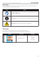
Safety Definitions Reliance Controls ARL Series Automatic Transfer Switch Safety Symbols Some of the following symbols may be used on this product. Please study them and learn their meaning. Proper interpretation of these symbols will allow you to more safely operate the product. SYMBOL MEANING Read Operator’s Manual. To reduce the risk of injury, user must read and understand operator’s manual before using this product. Ground Terminal.
SAFETY INSTRUCTIONS Reliance Controls ARL Series Automatic Transfer Switch SAFETY INSTRUCTIONS The Reliance Fast/Tran IS NOT FOR “DO-IT-YOURSELF” INSTALLATION. It must be installed by a qualified electrician thoroughly familiar with all applicable electrical and building codes. The Reliance Fast/Tran is an automatic transfer switch purpose-designed to provide a safe and simple method of powering a dwelling from a permanently installed backup AC power source.
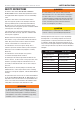
Reliance Controls ARL Series Automatic Transfer Switch SAFETY INSTRUCTIONS ATS Select Switch This unit may be wired to several models of ATS (automatic transfer switch). The selector switch is located onboard the generator near the ATS signal wire connector. Select position “1” if you are connecting to an ATS50 or ATS100 and select position “2” if you are connecting to a service entry demand control ATS (up to 200A).
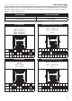
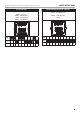
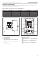
SAFETY INSTRUCTIONS Reliance Controls ARL Series Automatic Transfer Switch After March 2019, DIP switches on both the ATS and Engine Control Module will need to be adjusted differently due to a new revision E part number 100667 engine control module. This latest revision E is identified by a yellow box which also updates the software for 200A service entrance rated Reliance ATS. GENERATOR MODEL STARTING SERIAL NUMBER 100136 - 12.
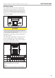
SAFETY INSTRUCTIONS Reliance Controls ARL Series Automatic Transfer Switch ATS DIP SWITCHES ENGINE CONTROL MODULE DIP SWITCHES 50A or 100A ATS: 100136 - 12.
Controls and Features Reliance Controls ARL Series Automatic Transfer Switch CONTROLS AND FEATURES Read this installation manual before installing your transfer switch. Familiarize yourself with the location and function of the controls and features. Save this manual for future reference.
Reliance Controls ARL Series Automatic Transfer Switch Controls and Features Installing the ARL Series Automatic Transfer Switch (ATS) Communication Wiring The ARL Series is a non-service entrance rated device and is not acceptable for use as service entrance. The NEMA 1 enclosure is only rated for indoor installation, models 100947 and 100949. The NEMA 3R enclosure is weather proof and rated for outdoor or indoor installation, models 100950 and 100952.
Controls and Features Reliance Controls ARL Series Automatic Transfer Switch TERMINAL BLOCK POSITION FUNCTION VOLTAGE COLOR CODE TB2-1 Switch to Generator Signal (+24 VDC) Blue TB2-2 Switch to Utility Signal (+24 VDC) Black/White Green TB2-3 Switch to – common return (0 VDC) TB2-4 (unused) (unused) TB2-5 Generator Position Micro Switch Switch closure Green/Black TB2-6 Utility Position Micro Switch Switch closure Yellow TB2-7 Position Micro Switch Common Switch closure Green T
Reliance Controls ARL Series Automatic Transfer Switch Line Voltage Wiring Controls and Features Use Copper Wire only, 75°C Minimum WARNING Be certain that the power from the utility is turned off and all backup sources are locked out before starting this procedure. Failure to do so could result in serious injury or death. Remember, automatic start generators will start upon loss of utility mains power unless locked in the “off” position.
Reliance Controls ARL Series Automatic Transfer Switch Controls and Features Circuit Breakers The ARL will accommodate tandem circuit breakers, but only in the four circuit breaker spaces closest to the transfer mechanism (The ones with the slotted bus stabs). The upper four locations are suitable only for full-size breakers. Recommended tandem breakers are the same as full size breakers listed on inside of entry door.
Reliance Controls ARL Series Automatic Transfer Switch Controls and Features Select ARL Circuits - Generator Select the circuits to be powered by the generator. Remove the selected breakers from the main panel. If the removed breakers are of an accepting type, install them in the ARL. If not,discard them and buy suitable breakers of the correct ampacity.
Fuse Information Reliance Controls ARL Series Automatic Transfer Switch Testing To assure the ARL is functioning properly 1. Turn OFF all of the distribution breakers in the ATS. 2. Manually switch the ATS to the utility position by moving the manual lever to the position marked Utility. figure 2). To access these screws, the branch circuit breakers will need to be pulled off (removed) from the bus bar first.
Fuse Information Reliance Controls ARL Series Automatic Transfer Switch Remove the voltmeter and reconnect the wires that were installed in terminals 11 and 12, in the correct order. Test F1. FOR NO MORE THAN 1 SECOND, press the positive lead of the 24VDC power supply to terminal 2. If the solenoid clicks and the mechanism transfers, fuse F6 is functional. If not replace fuse. Disconnect the 24VDC power supply and reconnect the wires that were installed in terminals 1, 2, and 3, in the correct order.
Reliance Controls ARL Series Automatic Transfer Switch Annual Maintenance 3. Remove mechanism from cabinet and turn upside down to expose fuses and replace fuse as necessary. If you have any questions, please call our Toll Free number at 1-877-338-0999. Thank you. ANNUAL MAINTENANCE The ARL should be maintained yearly. Visually inspect the unit to assure that there are no broken objects or loose wires in the cabinet.
Specifications Reliance Controls ARL Series Automatic Transfer Switch SPECIFICATIONS MODEL NUMBER ENCLOSURE STYLE MAXIMUM AMPS NOMINAL VOLTS BREAKER SPACES 100947 (ARL 0505) NEMA 1 indoor 50 120/240 8 100950 (ARL0505R) NEMA 3R outdoor 50 120/240 8 100949 (ARL 0909) NEMA 1 indoor 100 120/240 12 100952 (ARL0909R) NEMA 3R outdoor 100 120/240 12 LOCATION WIRE TORQUE Neutral bar 14-10 AWG 20 in. lb. Neutral bar 8 AWG Torque Ground bar 3 Position terminal strip 25 in. lb.