
ATS Installation Manual


RELIANCE CONTROLS ARL SERIES AUTOMATIC TRANSFER SWITCH
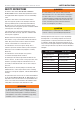
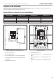
CONTROLS AND FEATURES
10
Installing the ARL Series Automatic
Transfer Switch (ATS)
The ARL Series is a non-service entrance rated device and
is not acceptable for use as service entrance. The NEMA 1
enclosure is only rated for indoor installation, models 100947
and 100949. The NEMA 3R enclosure is weather proof and
rated for outdoor or indoor installation, models 100950 and
100952.
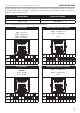
Removing NEMA 1 Dead Front
Removing NEMA 3
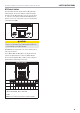
Communication Wiring
The communication terminal requires 10 wires.
Route a multi-conductor cable (min AWG 18 max AWG 12)
from the generator to the 12-position center Terminal Block in
the ARL through a smaller knockout. Strip wires 1/4 inch and
connect each numbered wire to the terminal block in sequence
from left to right starting with 1 in the left-most position.
Note that some of the terminal block positions are
deliberately left unused (TB2-4 and TB2-8.)
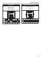
Each wire is connected by pushing the nylon release lever
backwards to open the terminal clamp, inserting the stripped
wire into the terminal opening, and releasing the terminal
clamp.
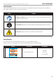
CAUTION
Care should be taken not to overstress the nylon release
levers.
NOTICE
See the table on page 8 for proper wire routing to both the
HSB connector and the ATS connector.
The 10-position communication terminal will connect to your
Home Standby. This connector is provided with the Home
Standby Generator. Cable is not provided.
CAUTION
Ensure power from the utility is turned off until all
communication wiring and line voltage wiring is complete.
Failure to comply may result in blown circuit board fuses,
which are not covered by warranty.