
ATS Installation Manual


RELIANCE CONTROLS ARL SERIES AUTOMATIC TRANSFER SWITCH
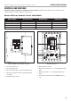
CONTROLS AND FEATURES
12
Line Voltage Wiring
WARNING
Be certain that the power from the utility is turned off
and all backup sources are locked out before starting this
procedure. Failure to do so could result in serious injury
or death. Remember, automatic start generators will start
upon loss of utility mains power unless locked in the “off”
position.
Consult the generator operator manual section to locate the
ATS CONTROL and ENGINE CONTROL module to make sure
both switches are in the OFF position.
CAUTION
Consult all local and National electrical codes for proper
wiring methods for all wiring.
Install a 50-amp double pole circuit breaker in the load center
(home distribution panel) as a feeder for the ATS for 50-amp
rated ARL.
Install a 100-amp double pole circuit breaker in the load center
(home distribution panel) as a feeder for the ATS for 100-amp
rated ARL.
Install, route and connect (Minimum 75°C) Black L1, and Red
L2 wire appropriate for 50-amp or 100-amp size (dependent on
ARL) between the double-pole feeder breaker in the load center
and the similarly-colored terminals on Utility Supply terminal
block in the ATS through a larger knockout. Strip wires 1/2 inch.
Use Copper Wire only, 75°C Minimum
Route and connect wire of the same AWG between the neutral
bar in the main panel and the White terminal on Utility Supply
terminal block in the ATS. Route and connect a ground wire
between the ground busses in the two panels.
Torque all line voltage connections to 25 in-lbs.