
ATS Installation Manual


RELIANCE CONTROLS ARL SERIES AUTOMATIC TRANSFER SWITCH
FUSE INFORMATION
15
Testing
To assure the ARL is functioning properly
1. Turn OFF all of the distribution breakers in the ATS.
2. Manually switch the ATS to the utility position by moving
the manual lever to the position marked Utility.
3. Turn ON the feeder breaker in the main panel board
4. Turn ON all distribution breakers and verify that all
connected circuits are functioning properly.
5. Remove the lockout apparatus and arm the HSB generator.
Your Fast/Tran ARL Series automatic transfer switch (ATS) is
now fully functional. To test its performance, simply disable
utility mains power.
Your generator should start and your ATS will automatically
switch to the “GENERATOR SUPPLY” source to power its
loads. When utility mains power is re-enabled, your ATS will
automatically switch back to “UTILITY SUPPLY” source.
Your generator will cool down, and turn off and then be placed
back into standby ready position.
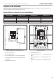
FUSE INFORMATION
Circuit Board – Fuses
WARNING
The power from “BOTH” the UTILITY power source and the
HSB “MUST” be turned “OFF” before attempting to identify
or replace any fuses. Failure to do so could result in serious
injury or death.
On the backside of the circuit board are six (6) BUSS AGC
fuses. F1 and F6 are 1.5 - amp slow blow fuses, and F2-F-5
are 6 amp fuses. Should any of these fuses blow, the generator
controller needs to be inspected and serviced by a qualified
technician. Once the cause of the blown fuse is resolved, the
fuse will need to be replaced. See fuse chart in transfer switch
for replacement fuse values.
To access the fuses on the rear of the circuit board, remove the
4 screws (parts 5 and 6, figure 2) from the mounting bracket,
and remove the two screws from the bus bar (parts 1 and 2,
figure 2). To access these screws, the branch circuit breakers
will need to be pulled off (removed) from the bus bar first. The
entire bus bar and mechanism assembly now can tilt away from
the cabinet (toward you), providing access to the rear of the
circuit board and the fuses.
Fuse identification, left to right:
6. F1 Utility Solenoid
7. F2 Utility L2 Out
8. F3 Utility L1 Out
9. F4 Load Bus L2 Out
10. F5 Load Bus L1 Out
11. F6 Generator Solenoid
Fuse Testing and Replacement
Test Fuses F2 and F3:
Disconnect the wires that are connected to terminals 9 and 10
on the 12-position terminal block.
With utility power on, verify the fact that all circuits connected
to the ATS are energized. Connect an AC voltmeter between
terminals 9 and 10. If the voltmeter reads approximately 240
VAC, fuses F2 and F3 are functional. If not inspect F2 and F3.
Replace one, or both fuse.
Remove the voltmeter and reconnect the wires that were
installed in terminals 9 and 10, in the correct order. Test F4 and
F5.
Test Fuses F4 and F5:
Disconnect the wires that are connected to terminals 11 and 12
on the 12-position terminal block. With utility power on, verify
the fact that all circuits connected to the ATS are energized.
Connect an AC voltmeter between terminals 11 and 12.
If the voltmeter reads approximately 240 VAC, fuses F4 and F5
are functional. If not inspect F4 and F5. Replace one, or both
fuse.