
ATS Installation Manual


RELIANCE CONTROLS ARL SERIES AUTOMATIC TRANSFER SWITCH
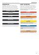
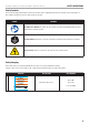
SAFETY INSTRUCTIONS
6
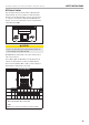
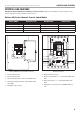
ATS Select Switch
This unit may be wired to several models of ATS (automatic
transfer switch). The selector switch is located onboard the
generator near the ATS signal wire connector. Select position
“1” if you are connecting to an ATS50 or ATS100 and select
position “2” if you are connecting to a service entry demand
control ATS (up to 200A).
1 2
CAUTION
Failure to set this switch to the matching ATS installed can
result in damage to both ATS and HSB.
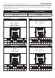
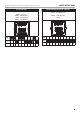
DIP SWITCHES on the backside of the control, between the 2
rows of pin connectors.
Prior to March 2019, the DIP switches set parameters of the
controller for delay sequences. There are 10 DIP switches.
These are the designated “ON” or “OFF” position settings for
the DIP switches, depending on your setup.
ATS DIP SWITCHES
ON
OFF
1 2 3 4 5 6 7 8 9 10
1- ON
2- ON for ATS 50/100 - OFF for ATS 200
3-9 OFF
10-ON-these are factory set delays or activation signals