Danger: Not intended for use in critical life support application. REV 100136-20200610 Danger: Generator must be installed and operated outdoors only.
Model 100136 INTRODUCTION PRODUCT REGISTRATION FREE OFFER! www.championpowerequipment.
WARNING Cancer and Reproductive Harm – www.P65Warnings.ca.gov DISCLAIMERS All information, illustrations and specifications in this manual are based on the latest information available at the time of publishing. The illustrations used in this manual are intended as representative reference views only. Products are under a continuous improvement policy.
Model 100136 CONTENTS CONTENTS PRODUCT REGISTRATION.....................................2 Battery Charger..............................................................20 Emission Requirements.................................................20 INTRODUCTION.....................................................6 Specifications.................................................................21 Home Standby Generator.................................................6 Fuel System..............................
Model 100136 CONTENTS TROUBLESHOOTING............................................43 Troubleshooting HSB......................................................43 ADDITIONAL INFORMATION................................45 Identify/Select Standby Circuits....................................45 Surge Protection............................................................45 Customer Familiarization Summary..............................46 HSB, ATS Model & Serial Reference ATS Back-up Circuits........................
Model 100136 INTRODUCTION Congratulations on your purchase of a Champion Power Equipment (CPE) home standby generator. This generator is designed and engineered in the USA to exacting standards of the North American market. This engine-powered generator meets all Environmental Protection Agency (EPA) Phase 3 requirements and is approved by CETLUS as tested to UL2200 and CSA22.2 No. 100 in both the USA and Canada.
Model 100136 INTRODUCTION GENERAL INFORMATION, STANDARDS AND CODES The following information related to General Information and Standards was gathered from the list of publications related to installing the HSB generator. A multitude of other materials related to generators were also used concerning common practice, knowledgeable installation practices, certified electrical experience and work related experiences.
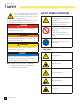
Model 100136 SAFETY ! This is the safety alert symbol. It is used to alert you to potential physical injury hazards. Obey all safety messages that follow this symbol to avoid possible injury or death. The words DANGER, WARNING, CAUTION and NOTICE are used throughout this manual to highlight important information.
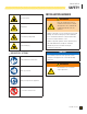
Model 100136 SAFETY INSTALLATION HAZARDS Explosion hazard Burn hazard Sever hazard (rotating blade) ! ! WARNING Have only a qualified electrician or installation technician who is familiar with applicable codes, standards and regulations install and service the generator. ALWAYS comply with local, state and national electrical and building codes when installing the generator. NEVER alter the recommended installation in a way that would render the unit noncompliant with these codes.
Model 100136 SAFETY BEFORE STARTING ! CAUTION Before starting, operating and maintaining this generator, be sure to read and understand the content and safety messages in this manual. The operator is responsible for safe operation and maintenance of the generator. Be sure all potential users of the generator also understand these instructions. If any portion of this manual is not understood, contact your dealer for assistance before operating the generator.
Model 100136 SAFETY ACCIDENTAL STARTING ! WARNING ALWAYS prevent the generator from starting while the covers are open. The generator may crank and start at any time without notice. Follow these steps in order: 1. Turn the exercise switch to the OFF position. 2. Switch the main circuit breaker to the OFF position. 3. Turn the ATS control module to the OFF position. 4. Turn the engine control module switch to the OFF position. 5.
Model 100136 SAFETY ELECTRICAL SHOCK HAZARDS ! WARNING FIRE/EXPLOSION HAZARDS ! WARNING Use extreme caution when near the generator while it is operating. The generator produces dangerous voltage. NG and LPG are extremely explosive. • Avoid contact with bare wires, terminals and connections while the generator is operating. • ALWAYS stand on an insulated dry surface to reduce shock hazard if work must be done on an operating generator. • NEVER allow any flames or smoke near the fuel system.
Model 100136 SAFETY ENTANGLEMENT HAZARDS ! SAFETY LABELS WARNING Use extreme caution when near rotating parts. Rotating parts can entangle hands, feet, hair, clothing and/or accessories. Traumatic amputation or severe laceration can result. • Keep hands and feet away from rotating parts. • Tie up long hair and remove jewelry. • Operate equipment with guards in place. • DO NOT wear loose-fitting clothing, dangling drawstrings or items that could become caught.
Model 100136 SAFETY SAFETY LABELS AND HANG TAGS # LABEL ! ! 1 Poisonous Gas Hazard Generator exhaust contains carbon monoxide. Breathing carbon monoxide will cause nausea, dizziness, and fainting, and it may cause death. ! 1 Fire Hazard ALWAYS keep the surrounding area near generator clean and free of debris and/or dry vegetation. The generator may create sparks while operating. Burn Hazard DO NOT touch hot surfaces. Avoid contact with exhaust components and gases.
Model 100136 SAFETY HANG TAG NOTICE AVISO AVIS DESCRIPTION PART NO. Service Entrance 1979-T-PR Alternate Power Source 1681-T-OP 1979-T-PR-A # NOTICE AVISO AVIS THIS CHAMPION HSB GENERATOR is set up for a 50/100A Select Circuit ATS. If you are using this with a 200A Service Entrance ATS model 101380, you will need to: ESTÉ GENERADOR CHAMPION HSB está configurado para un ATS de circuito selecto de 50/100A.
Model 100136 GENERAL INFORMATION COMPONENT IDENTIFICATION – 12.5 KW GENERATOR 9 3 5 4 2 6 1 7 8 10 11 12 Figure 1 16 1. Exhaust System 8. Engine Control Module 2. Alternator 9. Exterior Fault Code Indicator Light 3. Air Inlet 10. Fuel Regulator/Wire Connections (behind panel) 4. Main Circuit Breaker 11. Batteries (not included) 5. Hour Meter 12. Engine 6. Exercise Switch 7. ATS Control Module Part No.
Model 100136 GENERAL INFORMATION COMPONENT IDENTIFICATION – ENGINE 1 CONTROL PANEL MAIN CIRCUIT BREAKER The 52-amp main circuit breaker protects the generator from circuit overload. The main circuit breaker controls total output of the generator. (Figure 3) 2 MAIN CIRCUIT BREAKER 3 ON OFF 4 5 Figure 3 1. Engine Oil Dipstick 4. Spark Plug (second on opposite side) 2. Air Cleaner 5. Oil Filter 3. Oil Cap Figure 2 EXERCISE SWITCH The exercise switch incorporates a built-in timer.
Model 100136 GENERAL INFORMATION SET EXERCISE TIME To set the exercise time, the engine control module switch must be in the ATS mode. Decide on the desired day and time to exercise the generator. Press the exercise switch to ON. The generator will start and run for 15 minutes and then shut off. The exercise time is now set. The generator will begin the next exercise period exactly 168 hours from when the exercise switch was pressed to the ON position.
Model 100136 GENERAL INFORMATION HIGH ENGINE TEMP LED RUN LED The red LED will be lit if the engine operating temperature exceeds the factory preset limits. If excessive operating temperature is detected, the HSB will shut down and re-start will be disabled. The RED LEDs on the module and enclosure exterior are lit. The green LED will be lit indicating the engine is running. This failure could be the result of an excessive load or high ambient temperatures. Should this fault occur do the following; 1.
Model 100136 GENERAL INFORMATION BATTERY CHARGER EMISSION REQUIREMENTS The LEDs on the battery charger indicate the state of the battery’s charge level. Battery charger rating 24 Vdc 1.6A. (Figure 7) This engine-powered generator meets all United States Environmental Protection Agency (EPA) Phase 3 requirements and is approved for use in both the USA and Canada. POWER ALIMENTATION POTENCIA RECOGNIZED COMPONENT NO CHARGE / PAS DE CHARGE / SIN CARGA E. O.
Model 100136 GENERAL INFORMATION SPECIFICATIONS Home Standby Generator Maximum continuous power, LPG 12.5 kW Maximum continuous power, NG 11 kW Rated voltage 120/240 Amps 104/52 LPG (propane), 91.6/45.8 NG (natural gas) Harmonic distortion Less than 5% Main line circuit breaker 52 amp Phase Single Frequency 60 Hz Unit weight 425.5 lb. (193 kg) Size (L x W x H) 49 x 28 x 28 in. (124.5 x 71 x 71 cm) Engine Type Milwaukee Series OHV Commercial V-Twin No.
Model 100136 GENERAL INFORMATION FUEL SYSTEM BATTERY CHARGING The engine is fitted with a dual master mixer assembly carburetion system, which allows it to run on either NG or LPG. It has been configured at the factory to run on NG. If your installation requires the engine to run on LPG, orifices in the master mixer assembly carburetor must be changed. The generator is equipped with an automatic battery charger.
Model 100136 OPERATION Before operating the generator, review SAFETY section starting on page 8. PRE-START CHECKLIST ENCLOSURE AND ACCESS • Fuel valve is in the on position Open the enclosure to gain access to the generator and its components. (Figure 10) Unlock the handles. Turn the handles and lift the hoods up and to the outside.
Model 100136 MAINTENANCE ENGINE OIL Before performing maintenance procedures, review SAFETY section starting on page 8. Ensure that the ATS and Engine Switches are in the OFF position before performing any maintenance or cleaning. SCHEDULED MAINTENANCE CHART First 5 Hours of Operation Change engine oil Weekly Check exterior fault code indicator light Inspect and clean enclosure louvers √ Use American Petroleum Institute (API) Service Class SN or better. Do not use special additives.
Model 100136 MAINTENANCE 4. Remove the dipstick. The oil level should be at the FULL mark. If necessary, add oil. DO NOT overfill. 5. Position drain pan under alternator. 6. Loosen hose clamp on oil drain hose and slide drain hose off retaining pin. (Figure 13) 3 2 1 Figure 12 1. Oil Drain Hose 5. Install the dipstick. 6. Turn the engine control module switch to its prior position. CHANGING THE ENGINE OIL ! WARNING 2. Hose Clamp 3. Retaining Pin Figure 13 7.
Model 100136 MAINTENANCE INSPECT AND CLEAN ENGINE AIR CLEANER SPARK PLUG 1. Turn the ATS to the OFF position. 1. Turn the engine control module switch to the OFF position. 2. Turn the engine control module switch to the OFF position. 2. Unsnap the clips holding the air cleaner cover in place and remove the air cleaner cover. 3. Remove the spark plug cable from the spark plug. 4. Clean the area around the spark plug to keep dirt out of the engine and remove the spark plug. 5.
Model 100136 MAINTENANCE BATTERY MAINTENANCE 1. Turn the engine control module switch to the OFF position. 2. Inspect the battery cables and terminals for corrosion. 3. Check that the cables are securely fastened to the terminals. 4. Check the ground lug and make sure the connections are tight. 5. Check the fluid level of the battery, unless sealed. If low, top off the level using distilled water only.
Model 100136 MAINTENANCE RETURN TO SERVICE AFTER STORAGE 1. Make sure the utility power to the transfer switch is off. 2. The engine control module switch and the ATS control module switch should be in the OFF position. 3. Check the engine oil level. Add oil if needed. 4. Recharge the batteries to 100% state of charge. If the batteries will not fully charge, replace the batteries. ! ! WARNING Always connect the positive (+) battery cable first.
Model 100136 MAINTENANCE Page intentionally left blank Part No.
1 30 Part No.
Model 100136 MAINTENANCE # Part Number Description Part Number Description 101027 Cover, Fan, Rotating Screen With Oil Cooler Ribs 1 100928 Main Jet - Right 1 1 2 100929 Main Jet - Left 1 2 2.08.083 Bolt, Hex Flange M6 x 12 3 100910 Slow Jet - Right 1 6 4 100910 Slow Jet - Left 1 3 717.070004.00 Bracket, Fuel Pump 1 1 100909 Main Jet - Right 1 4 1.6177.20 Nut, M20 x 1.5 Flange 1 2 100310 Main Jet - Left 1 5 1.5789.
Model 100136 MAINTENANCE # Part Number Description Qty # Part Number Description 48 2.14.005 49 Key, Flywheel, 4 x 5.5 x 12.5 1 73 2.11.010 Seal, Pto Oil, Ø38 x Ø58 x 9 2 717.051101.04 Assembly, Crankshaft - Taper Pto 1 74 61.030011.00 Plug, Crankcase Cover 1 75 100699 Blade Assembly, Oil Dipstick 1 50 2.03.026 Washer, Crankshaft Thrust, Ø39 x Ø54 x 1.2 1 76 1.308.9.5 Ball Ø9.5, Steel Check Valve 1 51 101454 Camshaft Assembly 1 77 61.150004.
Model 100136 MAINTENANCE # Part Number Description Qty # 95 45.030200.00 96 2.06.013 Retainer, Oil Drain Hose 1 Hose Clamp, Ø13.5 x b10 1 97 45.032000.00 Hose, Oil Drain 1 98 1.276.6003.1 Bearing, Roller Ø35 x Ø17 x 10 1 99 717.030026.01 Plug, Npt1/8-27 Hexagon Socket 1 100 2.04.004 Pin, Ø12 x 20 Location 4 100170 Bracket, Governor Spring 1 101 Part Number Description Qty 120 1.6170.08 Hex Nut, Gb6170, M8 4 121 717.040016.00 Sleeve, Rocker Arm 4 122 2.08.
Part No.
Model 100136 MAINTENANCE # Part Number Description Qty 1 1.6177.1.06 Flange Lock Nut M6 24 # Part Number Description Qty 161.200021.17.6 Seal Strip, Top Cover, Long, 625 x 50 x 25 mm, Flame Retardant 1 2 1.5789.0615 Flange Bolt, M6 x 15 6 23 3 161.200507.00 Curb Chain Assembly, Cover 2 24 161.201600.02.1 Gutter, Black 1 25 161.100006.00 Spring, Muffler 3 4 163.200500.61.24 Top Cover Assembly, Right, Silk Grey, Flame Retardant and textured 1 26 2.08.
Model 100136 MAINTENANCE # Part Number Description 44 161.200300.60.24 Right Cover Assembly, Silk Grey, Flame Retardant and textured 1 45 161.201900.00 Hinge 4 46 161.134100.00 Solenoid Valve, LPG/NG 1 47 161.133106.01 Nipple, NPT 3/4 1 48 161.133106.00 Nipple, NPT 3/8 1 49 161.136000.00 Pressure Reducing Valve, LPG/NG 1 1 # Part Number Description Qty 66 161.200021.11.6 Foams, Front Cover, Flame Retardant 1 67 161.201800.00 Plastic Pallet, PP 1 68 163.200021.10.
Model 100136 MAINTENANCE Part No.
Part No.
Model 100136 MAINTENANCE # Part Number Description Qty # Part Number Description 1 100185 2 Qty Engine 1 30 161.201600.00 Supportor, Engine 1 161.190007.00 Front Housing, Stator 1 3 1.5789.1022 Flange Bolt, M10 x 22 4 31 163.080009.01.2 Air Guide, Muffler Pipe, Bottom 1 4 163.191100.00 Rotor Component, Ø135 x 160 1 32 1.96.08 Washer, Ø8 1 33 1.93.08 Lock Washer, Ø8 1 5 163.191002.00 Stator Cover 1 34 1.16674.0825 Flange Bolt, M8 x 25 1 6 163.191200.
22 21 23 40 Part No.
Model 100136 MAINTENANCE # Part Number Description 1 5.1600.010 Connector, Ten Holes, Male 1 2 5.1610.010 Connector, Ten Holes, Female 1 3 5.1810.007 Over Voltage Protector 1 4 1.818.0514 Screw, M5 x 14 3 5 161.210011.03 Terminal Block, 60A, 90° Angle 1 6 2.02.032 Cage Nut, M8 7 163.200004.60.24 Cover, Electric Cabinet, Silk Grey, Flame Retardant and textured 1 7 Qty # Part Number Description Qty 28 5.1820.003 Charger, Battery, 24V 1 29 1.9074.4.0414.
Model 100136 MAINTENANCE WIRING DIAGRAM 42 Part No.
Model 100136 TROUBLESHOOTING TROUBLESHOOTING HSB The number one problem which relates to starting, output and performance is “Fuel Pressure Insufficient”. Utility fuel regulator and pipe sized to small which can be compounded by pipe run distance to long for the size of pipe installed. Confirm fuel pressure to the fuel regulator during No-load and Load operation. ENGINE WILL NOT CRANK/TURN OVER 1 HSB set in “OFF” mode. Place the HSB controllers in the proper AUTO and ATS start positions.
Model 100136 TROUBLESHOOTING NO AC OUTPUT 1 HSB set in “TEST” mode Place HSB in AUTO and ATS mode. 2 Circuit breaker in “OFF” position Turn on breaker. 3 ATS control in “OFF” mode Place ATS module in ATS mode. 4 Main circuit breaker in “OFF” position. Turn on breaker. 5 Transfer switch breaker in “OFF” position. Turn on breaker. 6 Standby breakers set in “OFF” position. Turn on breaker.
Model 100136 ADDITIONAL INFORMATION IDENTIFY/SELECT STANDBY CIRCUITS IDENTIFY THE BASIC NEEDS It is very important to understand what items the home owner wants powered by the HSB during a utility failure. The selection of these items will indicate which circuits will be selected for connection to the ATS so that they are powered by the HSB.
Model 100136 ADDITIONAL INFORMATION CUSTOMER FAMILIARIZATION SUMMARY It’s important to educate the home owner on proper maintenance, operation and service call procedures. A properly educated home owner can reduce unnecessary service trips and phone calls. Ensure that the installation of the HSB and ATS has been correctly performed as outlined by the manufacturer and that it meets all applicable codes.
Model 100136 ADDITIONAL INFORMATION HSB, ATS MODEL & SERIAL REFERENCE ATS BACK-UP CIRCUITS HSB Model Number HSB Serial Number Fuel Type LPG ATS Model Number ATS Serial Number ATS circuits powered NG Date Installed Dealer/Installer Address Phone Cell Purchased from Part No.
Model 100136 ADDITIONAL INFORMATION MAINTENANCE AND SERVICE RECORD Keeping accurate records when any service is preformed is important. Records replace guessing when a repair was done or when it should be scheduled. Hour Meter notation as well as the date provides better time period records. To maintain the overall performance throughout the life of the product follow the scheduled maintenance chart contained in your owner’s manual or refer to www.championpowerequipment.com.
Champion Power Equipment 12039 Smith Ave.
10 Year Limited Warranty* Basic Warranty Provisions Champion Air-Cooled 8.
THIS WARRANTY SHALL NOT APPLY TO THE FOLLOWING: Original installation or start-up costs Champion Home Standby generators that utilize non-Champion Power Equipment replacement parts Costs of normal maintenance (i.e.
Costs incurred for equipment used for removal and/or reinstallation of generator, (i.e.: cranes, hoists, lifts, etc.) Planes, ferries, railroad, buses, helicopters, snowmobiles, snow-cats, off-road vehicles or any other mode of transport deemed abnormal Starting batteries, fuses, light bulbs, engine fluids, and spark plugs THIS WARRANTY AND THE ATTACHED U.S.
CHAMPION POWER EQUIPMENT, INC. (CPE) AND THE UNITED STATES ENVIRONMENT PROTECTION AGENCY (U.S. EPA) EMISSION CONTROL SYSTEM WARRANTY Your Champion Power Equipment (CPE) engine complies with U.S. EPA emission regulations. YOUR WARRANTY RIGHTS AND OBLIGATIONS: The US EPA AND CPE are pleased to explain the Federal Emission Control Systems Warranty on your 2020 small off-road engine (SORE) and engine powered equipment.
EMISSION CONTROL SYSTEM WARRANTY The following are specific provisions relative to your Emission Control System (ECS) Warranty Coverage. 1. APPLICABILITY: This warranty shall apply to 1997 and later model year small off-road engines (SORE). The ECS Warranty Period shall begin on the date the new engine or equipment is delivered to its original, end-use purchaser, and shall continue for 24 consecutive months thereafter. 2.
EMISSION-RELATED PARTS INCLUDE THE FOLLOWING: (using those portions of the list applicable to the engine) Systems covered by this warranty Parts Description Fuel Metering System Fuel regulator, Carburetor and internal parts Air Induction System Air cleaner, Intake manifold Ignition System Spark plug and parts, Magneto ignition system Exhaust System Exhaust manifold, catalytic converter Miscellaneous Parts Tubing, Fittings, Seals, Gaskets, and Clamps associated with these listed systems.