DANGER: Not intended for use in critical life support application. REV 100237-20171204 DANGER: Generator must be installed and operated outdoors only.
CALIFORNIA PROPOSITION 65 WARNING Certain components in this product and its related accessories contain chemicals known to the state of California to cause cancer, birth defects or other reproductive harm. Wash hands after handling. CALIFORNIA PROPOSITION 65 WARNING The engine exhaust from this product contains chemicals known to the state of California to cause cancer, birth defects or other reproductive harm.
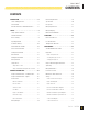
Model 100237 CONTENTS CONTENTS INTRODUCTION . . . . . . . . . . . . . . . . . . . . . . . . . . . 5 Emission Requirements . . . . . . . . . . . . . . . . . . . . 19 Home standby generator . . . . . . . . . . . . . . . . . . . . 5 Specifications . . . . . . . . . . . . . . . . . . . . . . . . . . . 20 Parts Included . . . . . . . . . . . . . . . . . . . . . . . . . . . 5 Fuel System . . . . . . . . . . . . . . . . . . . . . . . . . . . . 21 General information, Standards and Codes . . . . . . .
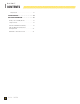
Model 100237 CONTENTS Wiring Diagram . . . . . . . . . . . . . . . . . . . . . . . . . . . 38 TROUBLESHOOTING . . . . . . . . . . . . . . . . . . . . . . . 39 ADDITIONAL INFORMATION . . . . . . . . . . . . . . . . . 41 Identify / Select Standby Circuits . . . . . . . . . . . . . 41 Surge Protection. . . . . . . . . . . . . . . . . . . . . . . . . 41 Customer Familiarization Summary . . . . . . . . . . . 42 HSB, ATS Model & Serial Reference Back-Up Circuits . . . . . . . . . . . . . . . . . . . . . . . .
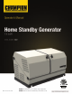
Model 100237 INTRODUCTION Congratulations on your purchase of a Champion Power Equipment (CPE) home standby generator. This generator is designed and engineered in the USA to exacting standards of the North American market. This engine-powered generator meets all Environmental Protection Agency (EPA) Phase 3 requirements and is approved by CETLUS as tested to UL2200 and CSA22.2 No. 100 in both the USA and Canada. With proper use and maintenance, this generator will provide years of satisfying service.
Model 100237 INTRODUCTION GENERAL INFORMATION, STANDARDS AND CODES The following information related to General Information and Standards was gathered from the list of publications related to installing the HSB generator. A multitude of other materials related to generators were also used concerning common practice, knowledgeable installation practices, certified electrical experience and work related experiences.
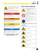
Model 100237 SAFETY ! This is the safety alert symbol. It is used to alert you to potential physical injury hazards. Obey all safety messages that follow this symbol to avoid possible injury or death. The words DANGER, WARNING, CAUTION and NOTICE are used throughout this manual to highlight important information.
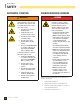
Model 100237 SAFETY INSTALLATION HAZARDS Explosion hazard Burn hazard ! ! WARNING Have only a qualified electrician or installation technician who is familiar with applicable codes, standards and regulations install and service the generator. ALWAYS comply with local, state and national electrical and building codes when installing the generator. NEVER alter the recommended installation in a way that would render the unit noncompliant with these codes.
Model 100237 SAFETY BEFORE STARTING ! OPERATING HAZARDS CAUTION Before starting, operating and maintaining this generator, be sure to read and understand the content and safety messages in this manual. The operator is responsible for safe operation and maintenance of the generator. Be sure all potential users of the generator also understand these instructions. If any portion of this manual is not understood, contact your dealer for assistance before operating the generator.
Model 100237 SAFETY ACCIDENTAL STARTING CARBON MONOXIDE HAZARDS WARNING ! ! ALWAYS prevent the generator from starting while the covers are open. The generator may crank and start at any time without notice. Follow these steps in order: 1. Turn the exercise switch to the OFF position. 2. Switch the main circuit breaker to the OFF position. 3. Turn the ATS control module to the OFF position. 4. Turn the engine control module switch to the OFF position. 5.
Model 100237 SAFETY Carbon monoxide poisoning is possible if someone is experiencing any of these symptoms. Seek fresh air immediately. DO NOT sit, lie down or fall asleep. Alert others to the possibility of carbon monoxide poisoning. If the affected person does not improve within minutes of breathing fresh air, call 911 immediately. ELECTRICAL SHOCK HAZARDS ! WARNING Use extreme caution when near the generator while it is operating. The generator produces dangerous voltage.
Model 100237 SAFETY BURN HAZARDS ! ! WARNING Batteries contain sulfuric acid and generate explosive mixtures of hydrogen and oxygen gases. Keep any device that may cause sparks or flames away from the battery to prevent explosion. ALWAYS allow hot surfaces to cool to the touch. Running engines produce heat. Severe burns can occur on contact. • DO NOT touch hot surfaces. Always wear protective glasses or goggles and protective clothing when working with batteries.
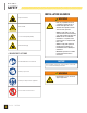
Model 100237 SAFETY SAFETY LABELS ON UNIT ! ! 1 Poisonous Gas Hazard Generator exhaust contains carbon monoxide. Breathing carbon monoxide will cause nausea, dizziness, and fainting, and it may cause death. ! Risque d’empoisonnement par le gaz Les gaz d’échappement de groupe électrogène contiennent du monoxyde de carbone. Si l’on respire du monoxyde de carbone, ceci peut provoquer des nausées, un évanouissement et une perte de conscience, et ceci peut provoquer la mort.
Model 100237 SAFETY SAFETY, SERIAL/MODEL, NAMEPLATE LABEL LOCATIONS The safety labels have specific placement and must be replaced if they are unreadable, damaged or missing. 4 1 ! (inner part of cover) 3 2 5 C A B 6 A) Serial number location B) Nameplate C) NFPA 37 Compliance 14 Part No.
Model 100237 GENERAL INFORMATION COMPONENT IDENTIFICATION – 14 KW GENERATOR 6 5 4 2 7 1 8 9 3 10 11 12 Figure 1 1. Exhaust System 7. Exercise Switch 2. Air Inlet 8. ATS Control Module 3. Fuel Regulator/Wire Connections (behind panel) 9. Engine Control Module 4. Main Circuit Breaker 11. Engine 5. Hour Meter 12. Alternator 6. Exterior Fault Code Indicator Light 10. Batteries (not included) Part No.
Model 100237 GENERAL INFORMATION COMPONENT IDENTIFICATION – ENGINE 2 CONTROL PANEL MAIN CIRCUIT BREAKER The 65 amp main circuit breaker protects the generator from circuit overload. The main circuit breaker controls total output of the generator. (Figure 3) 1 3 MAIN CIRCUIT BREAKER DISJONCTEUR PRINCIPAL INTERRUPTOR DE CIRCUITO PRINCIPAL ON MARCHE ENCENDIDO OFF ARRÊT APAGADO 4 5 Figure 3 Figure 2 1. Engine Oil Dipstick 2. Air Cleaner 3. Oil Cap 4. 5.
Model 100237 GENERAL INFORMATION SET EXERCISE TIME To set the exercise time, the engine control module switch must be in the ATS mode. Decide on the desired day and time to exercise the generator. Press the exercise switch to ON. The generator will start and run for 15 minutes and then shut off. The exercise time is now set. The generator will begin the next exercise period exactly 168 hours from when the exercise switch was pressed to the ON position.
Model 100237 GENERAL INFORMATION HIGH ENGINE TEMP LED The red LED will be lit if the engine operating temperature exceeds the factory preset limits. If excessive operating temperature is detected, the HSB will shut down and re-start will be disabled. The RED LEDs on the module and enclosure exterior are lit. POWER LED The green LED will be lit indicating the generator is working correctly and loads can be connected to it. This failure could be the result of an excessive load or high ambient temperatures.
Model 100237 GENERAL INFORMATION BATTERY CHARGER EMISSION REQUIREMENTS The LEDs on the battery charger indicate the state of the battery’s charge level. Battery charger rating 24 Vdc 1.6A. (Figure 7) This engine-powered generator meets all United States Environmental Protection Agency (EPA) Phase 3 requirements and is approved in both the USA and Canada. POWER ALIMENTATION POTENCIA RECOGNIZED COMPONENT NO CHARGE / PAS DE CHARGE / SIN CARGA E. O.
Model 100237 GENERAL INFORMATION SPECIFICATIONS Home standby generator Maximum continuous power, LPG 14 kW Maximum continuous power, NG 12.5 kW Rated voltage 120/240 Amps Harmonic distortion 116.6/58.3 LPG (propane), 104/52 NG (natural gas) Less than 5% Main line circuit breaker 65 amp Phase Single Frequency 60 Hz Unit weight 446.4 lb. (202.5 kg) Size (L x W x H) 49 x 28 x 28 in. (124.5 x 71 x 71 cm) Engine Type No.
Model 100237 GENERAL INFORMATION FUEL SYSTEM BATTERY CHARGING The engine is fitted with a dual master mixer assembly carburetion system, which allows it to run on either NG or LPG. It has been configured at the factory to run on NG. If your installation requires the engine to run on LPG, orifices in the master mixer assembly carburetor must be changed. The generator is equipped with an automatic battery charger.
Model 100237 OPERATION Before operating the generator, review SAFETY section starting on page 7. ENCLOSURE AND ACCESS Open the enclosure to gain access to the generator and its components. (Figure 10) Unlock the handles. Turn the handles and lift the hoods up and to the outside.
Model 100237 MAINTENANCE Before performing maintenance procedures, review SAFETY section starting on page 7. Ensure that the ATS and Engine Switches are in the OFF position before performing any maintenance or cleaning.
Model 100237 MAINTENANCE NOTICE DO NOT overfill the engine with engine oil. Damage to the engine may occur. 4. Remove the dipstick. The oil level should be at the FULL mark. If necessary, add oil. DO NOT overfill. NOTICE Always be environmentally responsible. Consult the local authorities or reclamations facility for proper disposal of engine oil waste. 5. Position drain pan under alternator. 6. Loosen hose clamp on oil drain hose and slide drain hose off retaining pin.
Model 100237 MAINTENANCE INSPECT AND CLEAN ENGINE AIR CLEANER 1. Turn the engine control module switch to the OFF position. 2. Unsnap the clips holding the air cleaner cover in place and remove the air cleaner cover. 3. SPARK PLUG 1. Turn the ATS to the OFF position. 2. Turn the engine control module switch to the OFF position. 3. Remove the spark plug cable from the spark plug. 4. Clean the area around the spark plug to keep dirt out of the engine and remove the spark plug. 5.
Model 100237 MAINTENANCE BATTERY MAINTENANCE 1. Turn the engine control module switch to the OFF position. 2. Inspect the battery cables and terminals for corrosion. 3. Check that the cables are securely fastened to the terminals. 4. Check the ground lug and make sure the connections are tight. 5. Check the fluid level of the battery, unless sealed. If low, top off the level using distilled water only.
Model 100237 MAINTENANCE RETURN TO SERVICE AFTER STORAGE 1. Make sure the utility power to the transfer switch is off. 2. The engine control module switch and the ATS control module switch should be in the OFF position. 3. Check the engine oil level. Add oil if needed. 4. Recharge the batteries to 100% state of charge. If the batteries will not fully charge, replace the batteries. ! ! WARNING Always connect the positive (+) battery cable first.
1 28 Part No.
Model 100237 MAINTENANCE # Part Number Description 1 101027 Cover, Fan, (Rotating Screen With Oil Cooler Ribs) 2 3 4 5 6 7 2.08.083 Bolt, Hex Flange M6 x 12 717.070004.00 1.6177.20 1.5789.0816 61.080005.00 717.080001.00 8 717.123000.03 9 10 100922 1.5789.0629 11 717.123000.04 Bracket, Fuel Pump Nut, M20 x 1.
Model 100237 MAINTENANCE # Part Number Description 96 97 98 99 100 101 102 103 104 105 106 107 108 109 110 111 112 113 114 115 116 117 2.06.013 45.032000.00 1.276.6003.1 717.030026.01 2.04.004 100170 2.01.010 717.010003.00 1.16674.0820 2.08.122 100179 717.040015.00 101881 45.040003.00 45.040001.00 717.040202.00 1.70.1.0816 22.040012.00 717.040200.02 101644 1.5789.0625 102357 1 2.07.001 2 101813 102261 21.040021.00 1.6170.08 717.040016.00 2.08.086 717.040005.00 45.040002.00 2.08.014 Hose Clamp, Ø13.
Model 100237 MAINTENANCE PAGE INTENTIONALLY LEFT BLANK Part No.
Part No.
Model 100237 MAINTENANCE # Part Number Description 1 2 3 1.6177.1.06 Flange Lock Nut M6 1.5789.0615 Flange bolt, M6 x 15 161.200507.00 4 164.200500.61.24 5 6 161.200110.00 161.200110.00.01 7 161.200021.16.6 8 9 1.16674.0820 1.16674.0812 10 161.200402.60.24 11 161.200109.63 12 164.200401.60.24 13 5.1460.015 14 161.192100.60 15 16 17 18 1.862.06 5.1560.000 717.090004.21 2.06.
Part No.
Model 100237 MAINTENANCE # Part Number Description 1 2 3 4 5 6 7 8 9 10 11 12 13 14 100206 161.190007.00 1.5789.1022 164.191100.00 164.191002.00 164.191200.00 161.190002.00 2.08.131 161.190300.00 122.190004.01 1.93.05 1.5783.0520 164.190001.00 1.5789.0629 15 2.08.
22 21 23 36 Part No.
Model 100237 MAINTENANCE # Part Number Description 1 2 3 4 5 6 5.1600.010 Connector, Ten Holes, Male Qty 1 5.1610.010 Connector, Ten Holes, Female 5.1810.007 1.818.0514 161.210011.02 2.02.032 7 163.200004.60.24 8 9 5.1000.006.3 5.1420.002 10 5.1241.965 11 12 13 14 15 16 17 18 5.1850.004 5.1850.003.Y 1.5789.0550 2.13.028 5.1850.005 2.08.068 161.200020.00 2.02.030 19 163.200005.60.24 20 163.200109.
Pink Purple White Green Orange B O G O/B Y GND G B/W Black/White L/B Blue/Black G/B N/C M Not Connect GND Start Motor G L/B B+ W B+ R 50W10Ω Power Resistance B/W Fuel Valve Fuel Valve N/C O/B Orange/Black G/B Green/Black R/B Red/Black G Br PART NO:101526.REV 1.2 P Pu Yellow Blue Y L G O W Red Black Brown R R B Battery Br GND B 24V R Stop ALT FUEL Start N/C R/B L/B IN.1 WATR OIL 8 7 6 L G/B Freq. Freq.
Model 100237 TROUBLESHOOTING TROUBLESHOOTING HSB The number one problem which relates to starting, output and performance is “Fuel Pressure Insufficient”. Utility fuel regulator and pipe sized to small which can be compounded by pipe run distance to long for the size of pipe installed. Confirm fuel pressure to the fuel regulator during No-load and Load operation. ENGINE WILL NOT CRANK/TURN OVER 1. HSB set in “OFF” mode. Place the HSB controllers in the proper AUTO and ATS start positions. 2.
Model 100237 TROUBLESHOOTING NO AC OUTPUT 1. HSB set in “TEST” mode. Place HSB in AUTO and ATS mode. 2. Circuit breaker in “OFF” position. Turn on breaker. 3. ATS control in “OFF” mode. Place ATS module in ATS mode. 4. Main circuit breaker in “OFF” position. Turn on breaker. 5. Transfer switch breaker in “OFF” position. Turn on breaker. 6. Standby breakers set in “OFF” position. Turn on breaker. 7. Line circuit tripping breaker because of short circuit * 8.
Model 100237 ADDITIONAL INFORMATION IDENTIFY/SELECT STANDBY CIRCUITS SURGE PROTECTION ! Identify the basic needs It is very important to understand what items the home owner wants powered by the HSB during a utility failure. The selection of these items will indicate which circuits will be selected for connection to the ATS so that they are powered by the HSB.
Model 100237 ADDITIONAL INFORMATION CUSTOMER FAMILIARIZATION SUMMARY It’s important to educate the home owner on proper maintenance, operation and service call procedures. A properly educated home owner can reduce unnecessary service trips and phone calls. Ensure that the installation of the HSB and ATS has been correctly performed as outlined by the manufacturer and that it meets all applicable codes.
Model 100237 ADDITIONAL INFORMATION HSB, ATS MODEL & SERIAL REFERENCE ATS BACK-UP CIRCUITS HSB Model Number _____________________________________ HSB Serial Number _____________________________________ Fuel Type LPG______________ NG________________ ATS Model Number ______________________________________ ATS Serial Number ______________________________________ ATS circuits powered ______________________________________ ____________________________ ____________________________ ___________________
Model 100237 ADDITIONAL INFORMATION MAINTENANCE AND SERVICE RECORD Keeping accurate records when any service is preformed is important. Records replace guessing when a repair was done or when it should be scheduled. Hour Meter notation as well as the date provides better time period records. To maintain the overall performance throughout the life of the product follow the scheduled maintenance chart contained in your owner’s manual or refer to www. championpowerequipment.com.
Champion Power Equipment 12039 Smith Ave.
10 Year Limited Warranty* Basic Warranty Provisions Champion Air-Cooled 8.
THIS WARRANTY SHALL NOT APPLY TO THE FOLLOWING: Original installation or start-up costs Champion Home Standby generators that utilize non-Champion Power Equipment replacement parts Costs of normal maintenance (i.e.
Costs incurred for equipment used for removal and/or reinstallation of generator, (i.e.: cranes, hoists, lifts, etc.) Planes, ferries, railroad, buses, helicopters, snowmobiles, snow-cats, off-road vehicles or any other mode of transport deemed abnormal Starting batteries, fuses, light bulbs, engine fluids, and spark plugs THIS WARRANTY AND THE ATTACHED U.S.
Champion Power Equipment, Inc. (CPE), United States Environment Protection Agency (U.S. EPA) Emission Control System Warranty Your Champion Power Equipment (CPE) engine complies with U.S. EPA emission regulations. YOUR WARRANTY RIGHTS AND OBLIGATIONS: The US EPA AND CPE are pleased to explain the Federal Emission Control Systems Warranty on your 2017 small off-road engine and engine powered equipment. New engines and equipment must be designed, built and equipped, at the time of sale, to meet U.S.
EMISSION CONTROL SYSTEM WARRANTY The following are specific provisions relative to your Emission Control System (ECS) Warranty Coverage. 1. APPLICABILITY: This warranty shall apply to 1997 and later model year small off-road engines. The ECS Warranty Period shall begin on the date the new engine or equipment is delivered to its original, end-use purchaser, and shall continue for 24 consecutive months thereafter. 2.
EMISSION-RELATED PARTS INCLUDE THE FOLLOWING: (using those portions of the list applicable to the engine) Systems covered by this warranty Fuel Metering System Fuel regulator, Carburetor and internal parts Air Induction System Air cleaner, Intake manifold Ignition System Spark plug and parts, Magneto ignition system Exhaust System Exhaust manifold, catalytic converter Miscellaneous Parts Tubing, Fittings, Seals, Gaskets, and Clamps associated with these listed systems.
Champion Power Equipment, Inc (CPE) and Environment and Climate Change Canada (ECCC) Emission Control System Warranty Your Champion Power Equipment (CPE) engine complies with Environment and Climate Change Canada (ECCC) emission regulations. YOUR WARRANTY RIGHTS AND OBLIGATIONS: CPE is pleased to explain the Emission Control Systems Warranty on your 2017 small off-road engine. New engines must be designed, built and equipped, at the time of sale, to meet ECCC regulations for small non-road engines.
EMISSION CONTROL SYSTEM WARRANTY The following are specific provisions relative to your Emission Control System Warranty Coverage. Emission Control System Warranty (ECS Warranty): 1. APPLICABILITY: The ECS Warranty Period shall begin on the date the new engine or equipment is delivered to its original, end-use purchaser, and shall continue for 24 consecutive months thereafter. 2.
EMISSION-RELATED PARTS INCLUDE THE FOLLOWING: (using those portions of the list applicable to the engine) Systems covered by this warranty Fuel Metering System Air Induction System Ignition System Exhaust System Miscellaneous Parts Evaporative Emissions Parts description Fuel regulator, carburetor and internal parts Air cleaner, intake manifold Spark plug and parts, magneto ignition system Exhaust manifold, catalytic converter Tubing, fittings, seals, gaskets, and clamps associated with these listed system