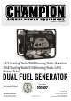
OWNER’S MANUAL 4375 Starting Watts/3500 Running Watts (Gasoline) 3950 Starting Watts/3150 Running Watts (LPG) Manual Start DUAL FUEL GENERATOR MODEL NUMBER U.S. Patent No. D710,802 SAVE THESE INSTRUCTIONS Important safety instructions are included in this manual. 100307 MADE IN CHINA REV 100307-20160725 12039 Smith Ave. Santa Fe Springs CA 90670 USA / 1-877-338-0999 www.championpowerequipment.
AN IMPORTANT MESSAGE ABOUT TEMPERATURE: Your Champion Power Equipment product is designed and rated for continuous operation at ambient temperatures up to 40°C (104°F). When your product is needed your product may be operated at temperatures ranging from -15°C (5°F) to 50°C (122°F) for short periods. If the product is exposed to temperatures outside this range during storage, it should be brought back within this range before operation.
100307 4375 Starting Watts/3500 Running Watts (Gas) 3950 Starting Watts/3150 Running Watts (LPG) Manual Start DUAL FUEL GENERATOR TABLE OF CONTENTS Introduction . . . . . . . . . . . . . . . . . . . . . . . . . . . . Manual Conventions. . . . . . . . . . . . . . . . . . . . . . . Safety Rules . . . . . . . . . . . . . . . . . . . . . . . . . . . . Fuel Safety. . . . . . . . . . . . . . . . . . . . . . . . . . . Safety Label Locations . . . . . . . . . . . . . . . . . . Controls and Features . . . . . . .
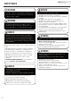
ENGLISH 100307 INTRODUCTION Congratulations on your purchase of a Champion Power Equipment product. Champion Power Equipment and Champion Engine Technology designs, builds, and supports all of our products to strict specifications and guidelines. With proper product knowledge, safe use, and regular maintenance, this product should bring years of satisfying service.
100307 ENGLISH MANUAL CONVENTIONS This manual uses the following symbols to help differentiate between different kinds of information. The safety symbol is used with a key word to alert you to potential hazards in operating and owning power equipment. Follow all safety messages to avoid or reduce the risk of serious injury or death. DANGER DANGER indicates an imminently hazardous situation which, if not avoided, will result in death or serious injury.
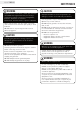
ENGLISH 100307 SAFETY RULES WARNING Read this manual thoroughly before operating your generator. Failure to follow instructions could result in serious injury or death. WARNING The engine exhaust from this product contains chemicals known to the state of California to cause cancer, birth defects, or other reproductive harm. DANGER Generator exhaust contains carbon monoxide, a colorless, odorless, poison gas. Breathing carbon monoxide will cause nausea, dizziness, fainting or death.
100307 ENGLISH WARNING Rapid retraction of the starter cord will pull hand and arm towards the engine faster than you can let go. Unintentional startup can result in entanglement, traumatic amputation or laceration. Broken bones, fractures, bruises or sprains could result. When starting engine, pull the starter cord slowly until resistance is felt and then pull rapidly to avoid kickback. DO NOT start or stop the engine with electrical devices plugged in.
ENGLISH 100307 SAFETY RULES Fuel Safety DANGER GASOLINE, GASOLINE VAPORS AND LIQUID PETROLEUM GAS (LPG) ARE HIGHLY FLAMMABLE AND EXPLOSIVE. Fire or explosion can cause severe burns or death. Unintentional startup can result in entanglement, traumatic amputation or laceration. Gasoline and Gasoline Vapors (Gas): – – – – GAS IS HIGHLY FLAMMABLE AND EXPLOSIVE. Gas can cause a fire or explosion if ignited. Gas is a liquid fuel but it’s vapors can ignite.
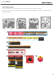
100307 ENGLISH SAFETY RULES Safety Label Locations These labels warn you of potential hazards that can cause serious injury. Read them carefully. If a label comes off or becomes hard to read, contact Champion Power Equipment’s customer service department for possible replacement. D A B C E F G F H A B WARNING Gasoline and it’s vapors are extremely flammable. Allow engine to cool at least 2 minutes before refueling.
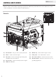
ENGLISH 100307 CONTROLS AND FEATURES Read this owner’s manual before operating your generator. Familiarize yourself with the location and function of the controls and features. Save this manual for future reference. Generator 1 8 9 2 7 3 6 4 7 5 (1) Gas fuel tank – 3.4 gal. (13 L) capacity fuel tank. (6) Oil filler cap – Check and fill engine oil level. (2) Choke – Used to start the engine. (7) Power panel – See “Power Panel” section.
100307 ENGLISH CONTROLS AND FEATURES Power Panel 1 4 2 5 (1) Fuel selector switch – Used to select and turn on gas or LPG fuel source. (2) Engine switch – Used to start or stop the generator. (3) Intelligauge – Three mode digital meter for displaying running hours, voltage and hertz. (4) LPG hose connector – Used to connect LPG hose to generator.
ENGLISH 100307 ASSEMBLY Your generator requires some assembly. This unit ships from our factory without oil. It must be properly serviced with fuel and oil before operation. If you have any questions regarding the assembly of your generator, call our help line at 1-877-338-0999. Please have your serial number and model number available. Add Engine Oil Cont’d. Remove the Generator from the Shipping Carton 1. Set the shipping carton on a solid, flat surface. 2.
100307 ENGLISH Add Engine Oil Cont’d. NOTE Weather will affect engine oil and engine performance. Change the type of engine oil used based on weather conditions to suit the engine needs. NOTE Synthetic oil may be used after the 5 hour initial break-in period. Using synthetic oil does not increase the recommended oil change interval. Full synthetic 5W-30 oil will aid in starting in cold ambient <5ºC (41ºF) Add Fuel (Gas) 1.
ENGLISH 100307 ASSEMBLY Connecting a LPG Cylinder 1. Make sure the fuel valve on the generator is in the off position. 2. Attach the LPG hose (included) to the LPG hose connector on the side of the generator and tighten with a 19 mm or adjustable wrench. Important: DO NOT use tape or any other type of sealant to seal LPG hose connection. 3. Remove the safety plug or cap from the cylinder valve. 4. Attach the other end of the hose to the LPG connector on the cylinder and hand tighten. 5.
100307 ENGLISH OPERATION Generator Location Grounding NEVER operate the generator inside any building, including garages, basements, crawlspaces and sheds, enclosure or compartment, including the generator compartment of a recreational vehicle. Please consult your local authority. In some areas, generators must be registered with the local utility. Generators used at construction sites may be subject to additional rules and regulations. Generators should be on a flat, level surface at all times.
ENGLISH 100307 OPERATION Fuel Selector Switch Starting the Engine in ambient > 15°C (59°F) The fuel selector switch on the front panel of the generator is designed specifically to choose between the fuel source desired, Gas or Propane (LPG). To select a fuel source simply slide the switch cover to either the right or left, and this will uncover the fuel valve of the fuel selected. The propane fuel valve (A) is to the left of the switch cover.
100307 ENGLISH OPERATION LPG Connecting Electrical Loads 1. Make certain the generator is on a flat, level surface. 2. Disconnect all electrical loads from the generator. Never start or stop the generator with electrical devices plugged in or turned on. 3. Fully open the LPG cylinder fuel knob. 4. Turn the LPG fuel valve to the “ON” position. 5. Move the choke lever to the “75% Choke” detent position. a. For restarting a warm engine, move the choke lever to the “75% CHOKE” detent position. 6.
ENGLISH 100307 OPERATION Do Not Overload Generator Capacity Follow these simple steps to calculate the running and starting watts necessary for your purposes. 1. Select the electrical devices you plan on running at the same time. 2. Total the running watts of these items. This is the amount of power you need to keep your items running. 3. Identify the highest starting wattage of all devices identified in step 1. Add this number to the number calculated in step 2.
100307 ENGLISH OPERATION Stopping the Engine Operation at High Altitude 1. Turn off and unplug all electrical loads. Never start or stop the generator with electrical devices plugged in or turned on. 2. Let the generator run at no-load for several minutes to stabilize internal temperatures of the engine and generator. 3. Turn the fuel valve to the “OFF” position if operating by gas. 4. Turn the LPG cylinder knob to the “CLOSE” or off position if operating by LPG. 5.
ENGLISH 100307 MAINTENANCE AND STORAGE The owner/operator is responsible for all periodic maintenance. WARNING Never operate a damaged or defective generator. WARNING Oil Cont’d. NOTE Once oil has been added, a visual check should show oil about 1-2 threads from running out of the fill hole. If using the dipstick to check oil level, DO NOT screw in the dipstick while checking. Tampering with the factory set governor will void your warranty. WARNING Improper maintenance will void your warranty.
100307 ENGLISH MAINTENANCE AND STORAGE Spark Arrester Maintenance Schedule 1. Allow the engine to cool completely before servicing the spark arrester. 2. Remove the three screws holding the cover plate which retains the end of the spark arrester to the muffler. 3. Remove the spark arrester screen. 4. Carefully remove the carbon deposits from the spark arrester screen with a wire brush. 5. Replace the spark arrester if it is damaged. 6.
ENGLISH 100307 MAINTENANCE AND STORAGE Storage The generator should be started at least once every 14 days and allowed to run for at least 20 minutes. For longer term storage, please follow these guidelines. Generator Storage 1. Add a properly formulated fuel stabilizer to the gas tank. 2. Be sure all appliances are disconnected from the generator. 3. Run the generator for a few minutes so the treated fuel cycles through the fuel system and carburetor. 4. Turn the gas fuel valve to the “Off” position. 5.
100307 ENGLISH SPECIFICATIONS Engine Specifications – – – – Model . . . . . . Displacement . Type . . . . . . . Start Type . . . . . . . . . . . . . . . . . . . . . . . Maintenance Valve Clearance . . . . . . . . . . . . . . . . . . . . . . . . . . . . . . . . . . . . . . . . . . . . YF172FD-L_G . . . . . .224cc .4-Stroke OHV . Manual Start Generator Specifications An Important Message About Temperature – – – – – – – – Model . . . . . . . . . . . .
21 53 52 51 50 83 86 85 80 81 82 84 78 79 77 76 75 87 74 71 88 89 73 72 90 70 69 68 67 49 66 65 91 64 92 63 48 93 42 60 59 58 57 56 55 47 94 62 54 51 95 38 96 61 1 98 2 41 97 110 101 100 99 109 105 104 103 102 29 107 106 3 43 42 4 40 45 44 39 46 5 6 30 29 28 27 7 38 26 8 108 25 9 10 24 31 32 33 34 35 36 37 11 23 12 14 13 22 16 21 17 20 19 15 18 10 SPECIFICATIONS ENGLISH 100307 Parts Diagram
100307 ENGLISH Parts List # Part Number Description Qty # Part Number Description Qty 1 27.491 Engine 1 59 1.93.06.2 Lock Washer Ø6 1 2 122.190005.00 Rubber, Fore-Cover, B 1 60 1.62.06 Butterfly Type Nut M6 1 3 122.190005.01 Rubber, Fore-Cover, A 1 61 2.05.005 Clamp Ø6 1 4 124.191100.02 Rotor Assembly, Al, Ø160 x 130 mm, CSA 1 62 2.05.009 Clamp Ø12.5 x 7 1 5 2.08.109 Flange Bolt M8 x 252 1 63 1.845.3513 Screw ST3.5 x 13 2 1.819.1.
23 1 17 89 19 2 3 4 5 6 7 8 9 10 15 18 25 21 23 24 100 103 1 98 54 49 50 51 102 52 53 101 48 12 13 26 27 29 30 26 32 35 45 37 64 20 22 99 38 12 55 56 57 58 14 40 41 31 60 61 62 12 59 16 28 51 42 63 34 19 39 43 44 72 106 92 46 83 82 80 81 79 78 74 73 76 105 71 70 69 68 67 66 65 36 33 77 107 11 88 87 86 85 84 97 91 104 90 75 47 93 94 95 25 96 SPECIFICATIONS ENGLISH 100307 Engine Parts Diagram
100307 ENGLISH # Part Number Description Qty # Part Number Description 1 1.5789.0608 Flange Bolt M6 x 8 4 60 25.040013.00 Lifter, Valve 2 22.061100.00.2 Cover, Recoil Starter, Black 61 2.04.001 Dowel Pin Ø9 x 14 3 21.061005.00 Spring, Recoil Starter 4 2.10.003 Rope Ø5 x 1550 5 21.061001.01 Reel, Recoil Starter 6 45.060003.00 7 45.060002.00 Starter Ratchet, Steel 8 45.060009.00 Spring Guide, Ratchet 1 1 1 1 2 2 1 1 1 1 8 1 1 1 1 1 1 1 Spring, Ratchet 9 45.060007.
25 a c e SWITCH d 1 2 3 4 f BLACK Br BROWN B Y YELLOW B/W BLACK WHITE BLUE W/G WHITE GREEN L GREEN G/Y GREEN YELLOW G W/L WHITE BLUE R RED W WHITE B/G BLACK GREEN ON OFF COMBINATION SWITCH LPG GAS b GENERATOR BLOCK FW MW2 ENGINE BLOCK W R + Y Y L L SPARKING PLUG EXW Br L Y Y B MW1 R R w IGNITION COIL B 4 3 Br Br CHARGE COIL 2 Charger 1 G/Y G/Y AVR w intelligauge G/Y L B w OIL LEVEL SW Y Y Y VFO DIODE w 120V TT-30R B B d a b W/G f c e G/Y w
100307 ENGLISH TROUBLESHOOTING Problem Cause Solution Generator will not start No fuel Add fuel Faulty spark plug Replace spark plug Unit loaded during start up Remove load from unit Low oil level Fill crankcase to the proper level Generator will not start; Generator starts but runs roughly Generator shuts down during operation Generator cannot supply enough power or overheating No AC output Repeated circuit breaker tripping Place generator on a flat, level surface Choke in the wrong posi
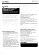
WARRANTY WARRANTY* CHAMPION POWER EQUIPMENT 2 YEAR LIMITED WARRANTY Warranty Qualifications Champion Power Equipment (CPE) will register this warranty upon receipt of your Warranty Registration Card and a copy of your sales receipt from one of CPE’s retail locations as proof of purchase. Please submit your warranty registration and your proof of purchase within ten (10) days of the date of purchase.
Champion Power Equipment, Inc. (CPE), The United States Environment Protection Agency (U.S. EPA.) and the California Air Resources Board (CARB) Emission Control System Warranty Your Champion Power Equipment (CPE) engine complies with both the U.S. EPA and state of California Air Resources Board (CARB) emission regulations.
EMISSION CONTROL SYSTEM WARRANTY The following are specific provisions relative to your Emission Control System (ECS) Warranty Coverage. 1. APPLICABILITY: This warranty shall apply to 1995 and later model year California small off-road engines (for other states, 1997 and later model year engines). The ECS Warranty Period shall begin on the date the new engine or equipment is delivered to its original, end-use purchaser, and shall continue for 24 consecutive months thereafter. 2.
EMISSION-RELATED PARTS INCLUDE THE FOLLOWING: (using those portions of the list applicable to the engine) Systems covered by this warranty Fuel Metering System Fuel regulator, Carburetor and internal parts Air Induction System Air cleaner, Intake manifold Ignition System Spark plug and parts, Magneto ignition system Exhaust System Exhaust manifold, catalytic converter Miscellaneous Parts Tubing, Fittings, Seals, Gaskets, and Clamps associated with these listed systems.