
Operators Manual

4
100398 ENGLISH
ASSEMBLY
Your snow plow requires some assembly.
If you have any questions regarding the assembly of your
snow plow, call our help line at 1-877-338-0999. Please
have your serial number and model number available.
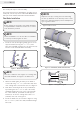
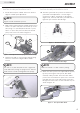
1. Install the left (6) and right (5) blade gussets to the
support bracket (2) using the
5
⁄16 ×
3
⁄4 in. (7.9 ×
19.1 mm) standard carriage bolts (7.1) and nuts (7.2).
This will create the blade frame assembly.
Plow Blade Installation
Figure 1 - Blade Frame Assembly
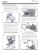
Figure 2 - Cutter Blade, Frame and Feet Install
Figure 3 - Carriage Bolt Diagram
Before starting the assembly of the blade and tubes
see Hybrid Mount installation instructions to ensure
it will work with your ATV.
NOTE
Install all hardware loose at first. Once all hardware
is correctly installed, tighten all bolts.
NOTE
There are 2 different neck lengths on a carriage bolt,
short and standard. See Figure 3 for differences.
NOTE
Adjust the feet by loosening the nuts and sliding
the feet up and down to the desired position. Start
with feet in minimum height position and adjust for
type of ground surface.
NOTE
7.1
7.2
5
2
6
SHORT NECK
CARRIAGE BOLT
STANDARD
CARRIAGE BOLT
7.5
7.1, 7.3, 7.4
7.2
7.5
7.2
7.2
7.4
7.3
A
7.4
3
4
1
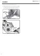
2. Attach the blade frame assembly to the blade in
location (A) using
5
⁄16 ×
3
⁄4 in. (7.9 × 19.1 mm) short
neck carriage bolts (7.5) and nuts (7.2). See Figure 2.
3. Next attach the wear bar (4) to the plow blade (1)
by installing the five
5
⁄16 × 1 in. (7.9 × 25.4 mm)
standard carriage bolts (7.3) in the center through
the cutter blade (4), plow blade (1) and support
bracket (2). Secure the carriage bolts with
5
⁄16 in.
(7.9 mm) nuts (7.2). See Figure 2.
4. Install the blade feet (3) as shown in Figure 2 using
the
5
⁄16 × 1
1
⁄4 in. (7.9 × 31.8 mm) standard carriage
bolts (7.4).
5. Tighten down all bolts.
Plow Blade Installation Cont’d.