
Operators Manual


6
100398 ENGLISH
ASSEMBLY
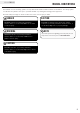
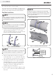
Figure 9 - Pitch Adjustment Bolt (spring not shown for clarity)
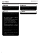
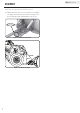
Figure 12 - Tube System Attachment
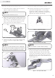
Figure 11 - Blade Rotation Angle
Figure 11-A - Blade Rotation Angle
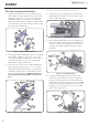
Figure 10 - Spring Adjustment
Default
11
15.7
15.6
11
3/4” DEFAULT
15.12
15.9
15.11
7. Decide desired pitch of blade. Each hole allows 5
degrees of blade pitch adjustment.
Push Tube Assembly and Installation Cont’d. Push Tube Assembly and Installation Cont’d.
Figure 9 shows the default position.
NOTE
Make sure handle is locked in before plowing.
NOTE
For each
1
⁄4 in. (6.4 mm) that the nut is tightened
it will add 7 lbs (3.2 kg) of spring tension. This will
make a total of 14 lbs (6.4 kg) with both springs.
NOTE
8. With springs installed and pitch blade under tension,
install
3
⁄4 in. (19.1 mm) hex socket head cap screw
(15.7) using
3
⁄8 in. (9.5 mm) Allen wrench or pliers;
and
7
⁄16 in. (11.1 mm) lock nut (15.6) into desired
pitch position hole. As shown in Figure 9.
9. Tighten nuts down on eye bolt until desired spring
tension is reached. See Figure 10 for default
tension.
10. The tube system has five positions of rotation for
your blade. Each adjustment is a 12.5 degree
increment. To adjust, push down on the handle
(Figure 11-A, Item 11) and rotate your blade left or
right until you reach the desired angle.
11. Attach the tube system to the Hybrid Mount System,
by first positioning the tube system, with blade
installed, under your ATV. Then raise tube attach
points to the mount and line up the holes on mount
plate with the holes in the tube system. Insert Pin
through holes and secure on other side with clips as
shown in Figure 12.
3/4 in. (19.1 mm)
default