
Use and Care Manual


100434 - 24 IN. 2-STAGE SNOWBLOWER
ASSEMBLY
14
ASSEMBLY
Your snowblower requires some assembly. This unit ships from our
factory without oil. It must be properly serviced with fuel and oil
before operation.
If you have any questions regarding the assembly of your
snowblower, call our Technical Support Team at 1-877-338-0999.
Please have your serial number and model number available.
Unpacking
1. Set the shipping carton on a solid, flat surface.
2. Remove everything from the carton except the snowblower
base — including upper and lower handles, wheels,
connecting levers, chute, hardware, etc. Make sure all the
assembly parts are included before you start.
3. Lift the top half of the box off and the base should be clear to
start assembly.
4. Cut down the bottom carton to allow a flat surface area to
install the assembly parts without scratching parts or cutting
tires. Alternatively, with team lift help, lift the base of the
snowblower out of the carton and place it on a flattened
carton to start assembly.
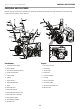
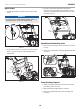
Lower Handle
1. Attach the lower handle (1-1) onto the unit body with bolts
(1-2, 1-3) and washers (1-4) (Fig. 1). Repeat on the other side.
NOTICE
Discharge chute bracket mounting hole should be on the left
side from the back of the snowblower.
1–1
1–2
1–4
1–3
Figure 1
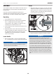
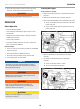
Wheel
1. Slide the left wheel (2-1) onto axle (2-2) as the arrow shows.
Tread pattern should face forward. Place axle pin (2-3) into
wheel. The axle has a center hole to attach the wheel to the
axle (which connects to the drive train). Once inserted, fold
ring around axle to hold in place (Fig. 2).
2–1
2–3
2–2
2–2
Figure 2
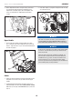
2. Repeat on right side. Tread pattern should face forward.
NOTICE
Only the left axle has two holes, and the axle pin can be
removed and repositioned. If the wheel is slid further in on the
axle with the pin inserted into the outside hole of the axle, the
machine will move freely without the engine on. If the pin is
inserted into the inside hole of the axle, the machine will only
move when the drive control is engaged when the engine is on.
It is optional to slide one wheel past the pin hole in the axle
and to place the locking pin into the axle outside the wheel
without locking it into the drive axle. This creates a pivot wheel
that allows the operator to more easily turn the snowblower
during use by using the “free wheel” as a pivot point. Though
this makes turning easier, it decreases drive wheel traction by
50%.