
Use and Care Manual


100434 - 24 IN. 2-STAGE SNOWBLOWER
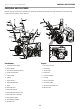
ASSEMBLY
15
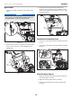
3. Attach adjustable skid shoes to auger housing. Insert bolts
(3-1) through the auger housing then through the shoe.
Tighten nuts (3-2) tightly (Fig. 3). Do not overtighten. The
shoe is not reversible. See “Adjusting the Snow Shoes”
section.
Adjusting skid shoe
3–1
3–2
Figure 3
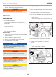
Upper Handle
1. Connect the upper handle and lower handle with 2 bolts
(4-1), 2 washers (4-2) and 2 locking knobs (4-3) only on the
bottom – keep them loose so you can fold the handle down in
the next step (Fig. 4).
4–1
4–2
4–3
Figure 4
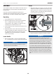
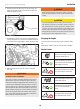
Cables
1. Cables are disconnected from each other and found near the
belt guard cover in front of the gas tank and on the upper
handle.
2. Fold handle down backwards (it will require some force to
fold backwards) and connect SELF-DRIVE CONTROL HANDLE
CABLE (5-1) on the right, and AUGER CABLE (5-2) on the left.
(Fig. 5).
3. Insert wire clamps (5-3) together and pull to make sure they
are connected. (Fig. 5).
5–3
5–2
5–1
Figure 5
NOTICE
The cables are preset by the factory. If you need to adjust
see ADJUSTING SELF-DRIVE CONTROL HANDLE CABLES or
ADJUSTING AUGER CONTROL CABLE for correct adjustments.
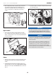
NOTICE
In the process of operation, if the auger or drive control handle
is too loose, screw the bolt of part A to get a natural tension
station for the wire.
Check the slack of the tension and adjust accordingly. You
want to make sure that the tension on the lower side of the
snowblower has
1
⁄4-
3
⁄8 in. (6.4-9.5 mm) of movement. If the
slack is greater than
5
⁄8 in. (16 mm), please adjust. Proper
tension is important because you will want your snowblower to
move forward properly in heavy snowfalls.