
Use and Care Manual
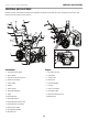


100434 - 24 IN. 2-STAGE SNOWBLOWER
ASSEMBLY
16
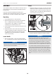
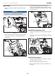
Upper Handle
1. Fold the upper handle up, making sure the cables pull tight
(Fig 6).
NOTICE
Do not bend the SELF-DRIVE CONTROL HANDLE CABLE (5-1)
and AUGER CABLE (5-2) bolts when folding upwards.
Figure 6
2. Connect the last 2 bolts (7-1), 2 washers (7-2) and 2 locking
k
nobs (7-3) on the top (Fig. 7). Fully hand tighten all four
locking knobs.
7–1
7–2
7–3
Figure 7
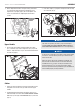
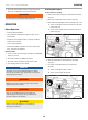
3. Discharge chute bracket should be placed forward as
shown (for correct placement). Do not overtighten. Connect
discharge chute guide to lower handle with 1 bolt (8-1), and 1
lock nut (8-2) (Fig. 8).
8–2
8–1
Figure 8
Speed Control Connecting Lever
1. Connect the connecting lever and connecting base with cotter
pin (9-1).
2. Connect the connecting lever and speed adjusting handle with
clip (Fig. 9).
9–1
Figure 9
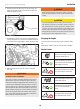
Snow Discharge Support
1. Remove the bolts (10-1) and nuts (10-2) from the main body
(Fig. 10). Set aside for next step.
2. Align snow discharge support with the main body.
3. Attach the snow discharge support on the main body with
bolts (10-1).