
Use and Care Manual
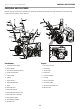


100434 - 24 IN. 2-STAGE SNOWBLOWER
OPERATION
19
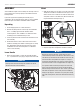
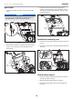
6. Stand back and to the right of the unit, pull the starter grip
lightly until you feel resistance then pull briskly. Return the
starter grip gently (Fig. 13C).
Starter grip
Figure 13C
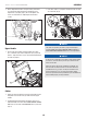
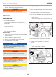
7. Alternatively for electric start, plug in the supplied electrical
cord into the starter. Press the electric start button and make
sure that the mains supply voltage is 120 V~ 60 Hz (Fig. 13D).
Electric start button
Figure 13D
8. When the engine starts, move the choke to run position
(Fig. 13B).
WARNING
GASOLINE IS HIGHLY FLAMMABLE.
Store fuel in containers specifically designed for this purpose.
Refuel outdoors only, before starting the engine, and do not
smoke while refueling or handling fuel. Never remove the cap
of the fuel tank or add gasoline while the engine is running or
when the engine is hot. If gasoline is spilled, do not attempt to
start the engine but move the machine away from the area of
spillage and avoid creating any source of ignition until gasoline
vapors have dissipated. Replace all fuel tanks and container
caps securely. Before tipping the snowblower to maintain the
blade or drain oil, remove fuel from tank.
WARNING
Never fill fuel tank indoors, with engine running, or until the
engine has been allowed to cool for at least 15 minutes after
running.
CAUTION
To prevent damaging the electric starter, do run it not more
than 10 times at intervals of 5 seconds on, then 5 seconds off.
If the engine does not start after this series of attempts, allow
the starter to cool for at least 40 minutes before trying to start
it again. If the engine still does not start, take the engine to an
authorized service center for service. Once started, disconnect
the plug from the power supply and the starter.
Stopping the Engine
To stop the engine in an emergency, simply remove the engine
key.
Under normal conditions move the fuel valve lever to the OFF.
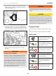
Control Levers
Self-drive control handle. Located on
the right side handle (Fig. 14).
When the snowblower has been put
into gear, pushing this lever towards the
handle engages the wheels.
Releasing the self-drive control handle
causes the machine to stop moving.
Auger control handle. Located on the
left side handle (Fig. 14).
Pushing this lever towards the handle
causes the auger and impeller to
activate.
Releasing the auger control handle
causes the auger to stop moving.