OPERATOR'S MANUAL MODEL #100468 Parallel Kit REGISTER YOUR PRODUCT ONLINE at championpowerequipment.com or visit championpowerequipment.com READ AND SAVE THIS MANUAL. This manual contains important safety precautions which should be read and understood before operating the product. Failure to do so could result in serious injury. This manual should remain with the product.
INTRODUCTION 100468 - Parallel Kit INTRODUCTION SAFETY DEFINITIONS Congratulations on your purchase of a Champion Power Equipment (CPE) product. CPE designs, builds, and supports all of our products to strict specifications and guidelines. With proper product knowledge, safe use, and regular maintenance, this product should bring years of satisfying service. The purpose of safety symbols is to attract your attention to possible dangers.
IMPORTANT SAFETY INSTRUCTIONS 100468 - Parallel Kit IMPORTANT SAFETY INSTRUCTIONS ! WARNING Cancer and Reproductive Harm – www.P65Warnings.ca.gov ! WARNING – ALWAYS turn the generator off and ensure the fuel valve is closed before connecting the parallel kit. – ALWAYS inspect for cut, torn or damaged extension cords before each use and if found DO NOT use. – NEVER use a parallel kit or its associated plug wires if cut, torn or damaged.
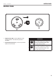
CONTROL PANEL 100468 - Parallel Kit CONTROL PANEL 1 2 B A 1. Output Indicator Light – Remains ON during normal operating conditions. Turns OFF when generator is overloaded. 2. Circuit Breaker (Push Reset) – Protects the generators against electrical overloads. RECEPTACLES A B t 120V AC, 30A RV (NEMA TT-30R) May be used to supply electrical power for operation of 120 Volt AC, 30 Amp, single phase, 60 Hz electrical loads.
ASSEMBLY AND OPERATION 100468 - Parallel Kit ASSEMBLY AND OPERATION This kit is intended for use on Champion Power Equipment inverters with ParaLINK ports. Please refer to your Inverter Operator’s Manual for safety rules, start up and shut down procedures, specifications and troubleshooting. " NOTICE Before parallel linking two inverters, visit the Parallel Kit Selector on championpowerequipment.com for compatibility. 5.
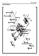
PARTS DIAGRAM 100468 - Parallel Kit 1 2 7 3 6 5 8 1 4 13 12 11 1 10 14 16 15 9 PARTS DIAGRAM 6
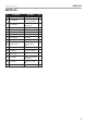
PARTS LIST 100468 - Parallel Kit PARTS LIST # Part Number Description Qty. 2.08.102 Tapping Screw 6×13 10 2 62.213004.00 Front Mounting Rubber, Base Setting 2 3 62.213004.01 Back Mounting Rubber, Base Setting 2 4 1.845.4216 Tapping Screw 4.2×16 4 5 62.213005.00 Base, Control Box 1 6 5.1900.106 Wire, black 2 7 62.213007.00.48 Door, Control Box 1 8 62.213008.00 Plate, Wire 1 9 62.213006.00 Cover,Control Box 1 10 1.9074.4.0512.
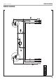
B BLACK G/Y GREEN YELLOW R RED G/Y B B R 120V TT-30R G/Y R R 30A R B R LED R 120V L5-30R B B G/Y 100468 - Parallel Kit WIRING DIAGRAM WIRING DIAGRAM 8
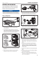
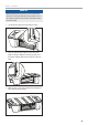
100468 - Parallel Kit " NOTICE While transporting the unit, there is a chance that the rear door panel can become detached from the parallel kit unit. If this happens, follow the steps below to reassemble the door panel to the body. 1. Line up left door hinge pin with left side pin socket. 2. Place the right side door hinge pin into the door frame guide slot. Using a steady force from the top right of the door panel, slide door down until the hinge pin snaps into place. 3.
WARRANTY CHAMPION POWER EQUIPMENT 1 YEAR LIMITED WARRANTY Warranty Qualifications To register your product for warranty and FREE lifetime call center technical support please visit: https://www.championpowerequipment.com/register To complete registration you will need to include a copy of the purchase receipt as proof of original purchase. Proof of purchase is required for warranty service. Please register within ten (10) days from date of purchase.