
Instruction Manual

7 REV 14560-20130415
ENGLISH 14560
ASSEMBLY
6. Splice the end of the red wire on the rocker
switch, to an ignition (keyed) controlled power
source using the supplied wire tap.
7. Once all wiring is connected to the solenoid/
contactor it can then be mounted using the
supplied M6 hardware.
8. Tighten the solenoid/contactor terminal nuts.
DO NOT over tighten.
9. Connect the black lead to the negative (–)
terminal of the vehicle’s 12 volt battery.
10. Place all terminal boots over terminals and
secure all cables with cable ties or electrical
tape (not included).
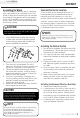
11. Check for proper drum rotation. Pull and turn
the clutch knob to the “OUT” position (free
spooling). Pull out some cable from the drum,
and then turn the clutch knob to the “IN”
position to engage the gears. Press the cable
out button on the rocker switch. If the drum
is turning and releasing more cable, then
your connections are accurate. If the drum
is turning and collecting more cable then
reverse the leads on the motor. Repeat and
check rotation.
Battery cables should NOT be drawn taut.
Leave some slack for cable movement.
CAUTION
Wireless Use Only
Non-Wireless Use Only
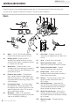
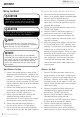
1. Connect the yellow and blue cables to the
motor terminals on the winch. (Yellow to the
positive (+) terminal of the motor. Blue to the
negative (-) terminal of the motor). Tighten
the terminal nuts on the motor. DO NOT over
tighten. Route the other ends to the solenoid/
contactor location.
2. Connect the yellow and blue cables to the
solenoid/contactor (yellow to yellow and
blue to blue). DO NOT tighten nuts.
3. Connect the red and black cables to the
solenoid/contactor (red to red and
black to black). DO NOT tighten nuts. Route
the other ends to the vehicle’s battery.
4. Connect the red lead to the positive (+)
terminal of the vehicle’s 12 volt battery.
5. Connect the rocker switch to the solenoid/
contactor (black to black and green to green).
Depending on the location of the solenoid/
contactor, you may need to use the black and
red cables in place of the yellow and blue, and
the yellow and blue in place of the red and
black. Just remember that this also changes
the diagram.
NOTE
You may need to use a test light to locate a
suitable wire. The wire should only have power
when the key is in the ON position.
NOTE
Wiring the Winch (Non-Wireless Use) Cont’d.
Wiring the Winch
NEVER route electrical cables across any
sharp edges, through and/or near moving
parts, or near parts that may become hot.
CAUTION