OWNER’S MANUAL AND OPERATING INSTRUCTIONS 7 Ton LOG SPLITTER MODEL NUMBER 90720 SAVE THESE INSTRUCTIONS Important Safety Instructions are included in this manual. MADE IN CHINA REV 90720-20131010 10006 Santa Fe Springs Road Santa Fe Springs CA 90670 USA / 1-877-338-0999 www.championpowerequipment.
AN IMPORTANT MESSAGE ABOUT TEMPERATURE: Your Champion Power Equipment product is designed and rated for continuous operation at ambient temperatures up to 40°C (104°F). When your product is needed your product may be operated at temperatures ranging from -15°C (5°F) to 50°C (122°F) for short periods. If the product is exposed to temperatures outside this range during storage, it should be brought back within this range before operation.
90720 7 Ton LOG SPLITTER TABLE OF CONTENTS Introduction . . . . . . . . . . . . . . . . . . . . . . . Introduction . . . . . . . . . . . . . . . . . . . . . Portable Log Splitter . . . . . . . . . . . . . . . Accessories . . . . . . . . . . . . . . . . . . . . . This Booklet . . . . . . . . . . . . . . . . . . . . . Manual Conventions. . . . . . . . . . . . . . . . . . Safety Rules . . . . . . . . . . . . . . . . . . . . . . . Training . . . . . . . . . . . . . . . . . . . . . . . . Preparation . . . . .
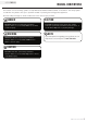
ENGLISH 90720 INTRODUCTION Introduction Accessories Congratulations on your purchase of a Champion Power Equipment log splitter. CPE designs and builds log splitters to strict specifications. With proper use and maintenance, this log splitter will bring years of satisfying service. Champion Power Equipment manufactures and sells accessories designed to help you get the most from your purchase. To find out more, please visit our website at: www.championpowerequipment.
90720 ENGLISH MANUAL CONVENTIONS This manual uses the following symbols to help differentiate between different kinds of information. The safety symbol is used with a key word to alert you to potential hazards in operating and owning power equipment. Follow all safety messages to avoid or reduce the risk of serious injury or death. DANGER DANGER indicates an imminently hazardous situation which, if not avoided, will result in death or serious injury.
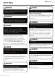
ENGLISH 90720 SAFETy RULES WARNING Read this manual thoroughly before operating your log splitter. Failure to follow instructions could result in serious injury or death. WARNING The engine exhaust from this product contains chemicals known to the state of California to cause cancer, birth defects, or other reproductive harm. DANGER Log Splitter engine exhaust contains carbon monoxide, a colorless, odorless, poison gas. Breathing carbon monoxide will cause nausea, dizziness, fainting or death.
90720 ENGLISH DANGER Skin Injection Hazard. High pressure hydraulic oil can inject under your skin. Make sure all fittings are tightly secure before applying pressure. Relieve system of pressure before servicing. WARNING Towing Hazard ALWAYS check all local and state regulations regarding towing, licensing and lights before towing your log splitter. Review towing safety warnings in your towing vehicle manual. Drive safely. Be aware of the added length of the log splitter.
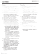
ENGLISH 90720 SAFETy RULES Training Preparation 1. 1. 2. 3. 4. 5. 6. 7. 8. 9. 10. 5 Read the Operator’s Manual completely before attempting to use this log splitter. Do not allow anyone to operate your log splitter who has not read the Operator’s Manual or has not been instructed on the safe use of the log splitter. Never allow children or untrained adults to operate this machine. Many accidents occur when more than one (1) person operates the log splitter.
0720 ENGLISH SAFETy RULES Operation Maintenance and Storage 1. 1. 2. 3. 4. 5. 6. 7. 8. 9. 10. 11. 12. 13. Before starting this log splitter, review all safety rules. Failure to follow these rules may result in serious injury to the operator or bystanders. Be sure to confirm all hose connections and hose clamps are tight before each use. It is possible for connections to vibrate loose over time. Never leave the machine unattended with the power source operating.
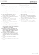
ENGLISH 90720 CONTROLS AND FEATURES Read this owner’s manual before operating your log splitter. Familiarize yourself with the location and function of the controls and features. Save this manual for future reference. Log Splitter 4 5 3 6 2 7 10 9 8 Back View 11 12 1 (1) Handle (7) Wheels (2) Wedge (8) Hydraulic Vent Screw – Vents hydraulic oil tank. (3) Engine – 80cc, OHV, 4-stroke, air cooled. (9) (4) Control Valve Handle – Controls the movement of the thrust plate.
90720 ENGLISH Your log splitter requires some assembly. If you have any questions regarding the assembly of your log splitter, call our help line at 1-877-338-0999. Please have your serial number and model number available. Open Shipping Crate 1. Set the shipping crate on a solid, flat surface 2. Carefully cut the shipping bands and remove lid of shipping crate. 3. Locate all hardware before beginning assembly. ASSEMBLy 3) Install the Beam onto the Wheel Mount 1. 2. 3. 4.
ENGLISH 90720 ASSEMBLy 5) Install the Cylinder to the Beam 7) Install the Handle 1. 1. Slide the handle (#31) into the tube bracket on the end of the beam. 2. Secure with clip ring (#32). 2. Slide the cylinder pegs into the cylinder mounting slots on the top of the beam. Secure the cylinder retention plates (#20) with M10x20 bolts (#23) M10 lock washers (#22) and M10 washers (#21). 8) Install the Hoses 1. NOTE The cylinder should extend in the opposite direction of the beam as shown.
90720 ENGLISH Add Engine Oil CAUTION DO NOT attempt to crank or start the engine before it has been properly filled with the recommended type and amount of oil. Damage to the log splitter as a result of failure to follow these instructions will void your warranty. 1. 2. 3. 4. Make sure the log splitter is on a flat, level surface. Remove oil fill cap/dipstick to add oil. Add up to 0.42 qt (0.4 L) of oil. Replace oil fill cap/ dipstick. DO NOT OVERFILL. Check engine oil level daily and add as needed.
ENGLISH 90720 ASSEMBLy Add Hydraulic Oil 1. 2. 3. 4. Add Hydraulic Oil Cont’d. Make sure the log splitter is on a flat, level surface. Remove the dipstick from the oil tank. (A) Using your fingers, open the hydraulic vent screw by turning it counter clockwise approximately 2-3 times. (B) Add 0.87 gal. (3.3 L) of hydraulic oil - 10W AW32, ASLE H-150, or ISO 32. NOTE When the outdoor tempurature is below 32 ˚F, Dexron III transmission fluid can be used. 5. Check the hydraulic oil level using dipstick.
90720 ENGLISH Before Each Use Inspect the Log Splitter 1. Check the hydraulic oil level and visually inspect all hoses, attachments and cylinder for loose fittings, leaks, cracks, fraying or other damage. 2. DO NOT operate the log splitter if there is any indication of damage. 3. Inspect the engine and make sure the oil level is correct before operating. If the engine is equipped with a spark arrestor, clean and inspect it regularly (follow spark arrestor maintenance schedule).
ENGLISH 90720 OPERATION Starting the Engine Cont’d. Starting the Engine 1. Make certain the log splitter is on a flat, level surface. 2. Using your fingers, open the hydraulic vent screw by turning it counter clockwise approximately 2-3 times. 3. Flip engine switch to “ON” position (Item A). 4. Rotate the fuel valve to the “ON” position (Item B). 5. Move the throttle lever (Item C) to the “Fast” position. 6. Move the choke lever (Item D) to the “Choke” position. 7.
90720 ENGLISH OPERATION Log Splitter Operation Cont’d. CAUTION Back injury can result from lifting logs onto the log splitter if proper lifting techniques are not used. 3. Load a log onto the beam against the wedge. 4. Make sure all limbs are clear of crush zones. 5. Push and hold the control valve handle forward (towards the wedge) to split the log. The wedge will stop when the control valve handle is released, or when the cylinder reaches the end of stroke. 6.
ENGLISH 90720 MAINTENANCE AND STORAGE The owner/operator is responsible for all periodic maintenance. WARNING Never operate a damaged or defective log splitter. WARNING Spark Plugs 1. 2. Remove the spark plug cable from the spark plug. Inspect the electrode on the plug. It must be clean and not worn to produce the spark required for ignition. 3. Make certain the spark plug gap is 0.7 - 0.8 mm (0.028 - 0.031 in.). Improper maintenance will void your warranty. 0.7 - 0.8 mm 0.028 - 0.031 in.
90720 ENGLISH MAINTENANCE AND STORAGE Cleaning Hydraulic Oil CAUTION DO NOT use a garden hose to clean the engine or log splitter. Water can contaminate the fuel system and can enter the engine through the cooling slots and damage the engine. Clear the debris from the beam, wedge and endplate. Use a damp cloth to clean exterior surfaces of the engine and log splitter. Use a soft bristle brush to remove excess dirt and oil. Use an air compressor (25 PSI) to clear dirt and small debris.
ENGLISH 90720 MAINTENANCE AND STORAGE Storage Refer to the Maintenance section for proper cleaning instructions. Log Splitter Storage DANGER 1. Engine exhaust contains odorless and colorless carbon monoxide gas.
90720 ENGLISH SPECIFICATIONS Hydraulic Oil System Log Splitter Specifications – – – – – – – – – – – – – – – – – Ram Force . . . . . . . . . . . . Cycle Time, Max . . . . . . . . Hydraulic Tank Capacity . . . Max Log Length . . . . . . . . Tire Size, Outside Diameter Engine . . . . . . . . . . . . . . . Cylinder size . . . . . . . . . . . Gear Pump . . . . . . . . . . . . Max pressure . . . . . . . . . . Max flow . . . . . . . . . . . . . Control Valve . . . . . . . . . . Overall Dimensions Gross Weight .
ENGLISH 90720 SPECIFICATIONS Parts Diagram 5 6 8 4 7 9 2 3 1 10 32 12 11 13 9 31 11 25 26 27 15 14 33 41 24 28 16 20 29 21 22 23 25 27 30 17 42 45 44 18 11 48 9 43 46 19 49 52 53 47 54 55 51 26 27 27 26 25 9 40 50 39 22 34 35 11 36 26 27 38 37 19 REV 90720-20131010
90720 ENGLISH Parts List # Part number Description Qty # Part number Description 1 GB/T 889.1-2000 Lock Nut M10 1 29 PMJ7-07 Rubber Damping Pad Qty 1 2 PMJ7-02 Bracket 1 30 GB/T 70.1-2000 Bolt M8×25 2 3 GB/T 5782-2000 Bolt M10×60 1 31 PMJ7-06 Handle 1 4 PMJ7-21 Control Valve 1 32 GB/T 91-2000 Cotter pin ø2x20 1 5 GB/T 818-2000 Bolt M6×10 2 33 PMJ7-20 Handle Sheath 1 6 GB/T 93-1987 Lock Washer ø6 2 34 GB/T 70.
21 REV 90720-20131010 102 101 100 99 98 97 1 96 16 2 103 17 3 4 4 83 5 18 95 3 94 93 92 91 6 20 7 21 75 76 77 19 79 19 82 22 8 78 80 81 23 9 24 25 26 10 11 27 28 12 30 29 31 13 55 73 13 56 74 14 32 72 84 57 33 1 15 58 34 71 59 60 35 61 70 62 36 19 63 85 69 37 39 24 40 16 64 38 41 41 42 43 44 68 45 35 66 46 67 47 66 65 54 48 49 86 87 50 51 88 89 52 90 53 3 SPECIFICATIONS ENGLISH 90720 Engine Parts D
90720 ENGLISH # Part Number Engine Parts List Description Qty # Part Number Description Qty 1 1.5789.0610 Flange Bolt M6×10 4 53 21.020001.00 Breather Tube 1 2 12.061000.02 Recoil Assembly 1 54 2.01.010 Stud Bolt (M8×35) 2 3 1.16674.0612 Flange Bolt M6×12 11 55 12.041000.01 Camshaft (EPA) 1 4 1.5789.0608 Flange Bolt M6×8 3 56 12.040013.00 Lifter, Valve 2 5 12.111000.00 Control Assembly 1 57 12.040005.00 Push Rod 2 6 12.080100.02.48 Fan Cover 1 58 12.
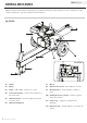
ENGLISH 90720 TROUBLESHOOTING Problem Cause Solution Engine will not start No fuel Add fuel Faulty spark plug Replace spark plug Unit loaded during startup Remove load from unit Low oil level Fill crankcase to the proper level Engine will not start; Engine starts but runs roughly Engine shuts down during operation Place log splitter on a flat, level surface Choke in the wrong position Adjust choke Spark plug wire loose Attach wire to spark plug Out of fuel Fill fuel tank Low oil level
90720 ENGLISH WARRANTy WARRANTy CHAMPION POWER EQUIPMENT 1-YEAR LIMITED WARRANTY Warranty Qualifications Champion Power Equipment (CPE) will register this warranty upon receipt of your Warranty Registration Card and a copy of your sales receipt from one of CPE’s retail locations as proof of purchase. Please submit your warranty registration and your proof of purchase within ten (10) days of the date of purchase.
Champion Power Equipment, Inc. (CPE), The United States Environment Protection Agency (U.S. EPA.) and the California Air Resources Board (CARB) Emission Control System Warranty Your Champion Power Equipment (CPE) engine complies with both the U.S. EPA and state of California Air Resources Board (CARB) emission regulations.
EMISSION CONTROL SYSTEM WARRANTY The following are specific provisions relative to your Emission Control System (ECS) Warranty Coverage. 1. APPLICABILITY: This warranty shall apply to 1995 and later model year California small off-road engines (for other states, 1997 and later model year engines). The ECS Warranty Period shall begin on the date the new engine or equipment is delivered to its original, end-use purchaser, and shall continue for 24 consecutive months thereafter. 2.
EMISSION-RELATED PARTS INCLUDE THE FOLLOWING: (using those portions of the list applicable to the engine) Systems covered by this warranty Fuel Metering System Fuel regulator, Carburetor and internal parts Air Induction System Air cleaner, Intake manifold Ignition System Spark plug and parts, Magneto ignition system Exhaust System Exhaust manifold, catalytic converter Miscellaneous Parts Tubing, Fittings, Seals, Gaskets, and Clamps associated with these listed systems.